
Module for wavelength monitoring in wavelength division multiplexing transmission network and implementation method

A technology of transmission network and wavelength division multiplexing, which is applied in the field of optical communication, can solve the problems of complex wavelength scanning method and high difficulty in device manufacturing, and achieve the effect of low device manufacturing difficulty, simple structure and simple scanning method

Pending Publication Date: 2019-08-20
易锐光电科技(安徽)有限公司 +1
View PDF0 Cites 0 Cited by
  • Summary
  • Abstract
  • Description
  • Claims
  • Application Information

AI Technical Summary

Problems solved by technology

[0006] This application provides a module and implementation method for wavelength monitoring in wavelength division multiplexing transmission networks, which can solve the problems of complicated wavelength scanning methods and high difficulty in device manufacturing

Method used


Image

  • Module for wavelength monitoring in wavelength division multiplexing transmission network and implementation method
  • Module for wavelength monitoring in wavelength division multiplexing transmission network and implementation method
  • Module for wavelength monitoring in wavelength division multiplexing transmission network and implementation method

Examples


Embodiment Construction

[0038] The specific implementation manners of the present application will be further described in detail below in conjunction with the drawings and embodiments. The following examples are used to illustrate the present application, but not to limit the scope of the present application.

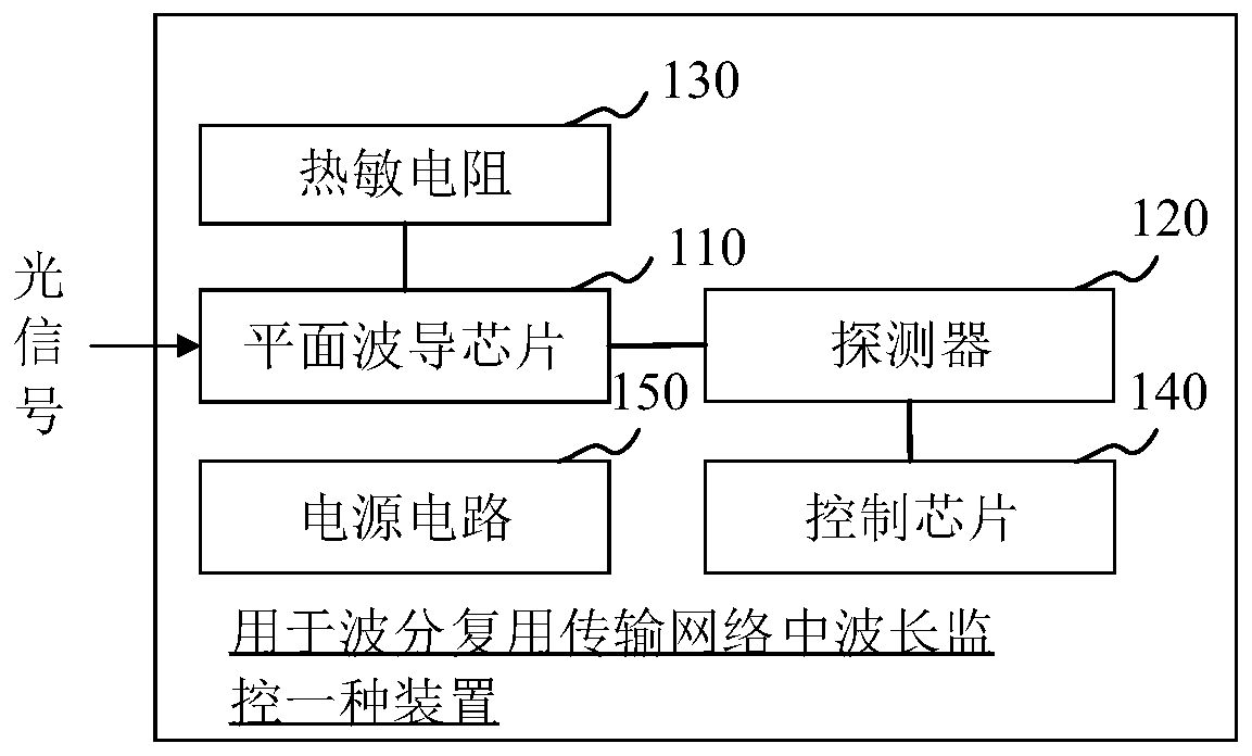
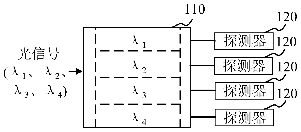
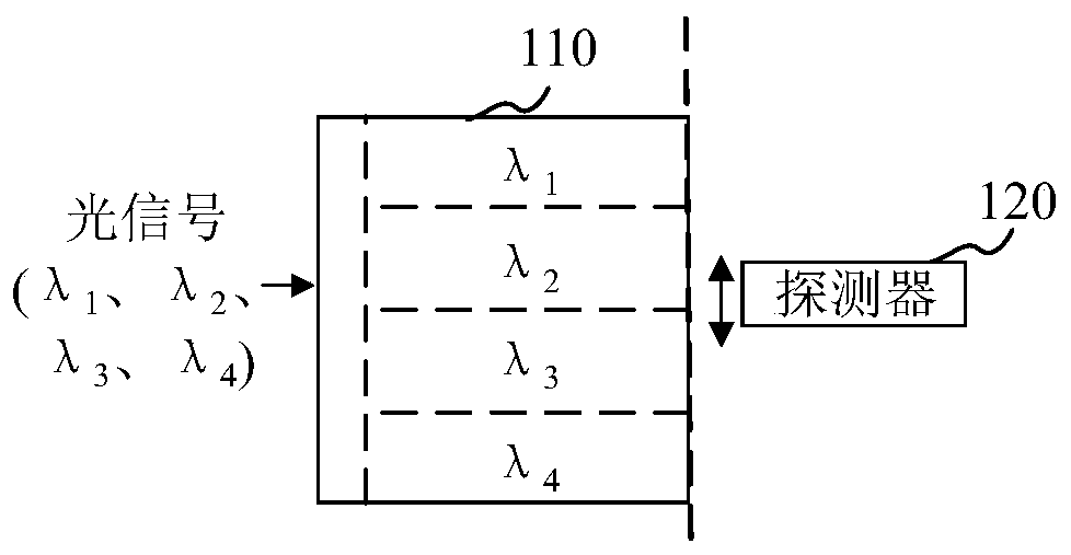
[0039] figure 1 It is a schematic structural diagram of a module used for wavelength monitoring in a wavelength division multiplexing transmission network provided by an embodiment of the present application, such as figure 1 As shown, the module at least includes: a planar waveguide chip 110 and at least one detector 120 .

[0040] The planar waveguide chip 110 has wavelength dispersion capability. The planar waveguide chip 110 includes an input terminal for inputting an optical signal and an output terminal for outputting an optical signal. Wherein, the input end may be formed by an input waveguide, and the output end may be formed by an output waveguide.

[0041] Optionally, the planar...


PUM


Abstract

The invention relates to a module for wavelength monitoring in a wavelength division multiplexing transmission network and an implementation method, and belongs to the technical field of optical communication. The module comprises a planar waveguide chip which has wavelength dispersion capability and is used for dispersing an optical signal which is received by an input end and has a plurality oftransmission wavelengths to a corresponding optical transmission channel; and at least one detector arranged on one side of the output end of the planar waveguide chip and used for determining the transmission wavelength of the dispersed optical signal according to the optical transmission channel corresponding to the dispersed optical signal. The problems that a wavelength scanning mode is complex and the device manufacturing difficulty is high can be solved. The wavelength detection function can be realized through the detector based on the dispersion characteristic of the planar waveguide,the signal power information can be obtained, the structure is simple, and the used element is a conventional chip. The scanning mode is simple and the device manufacturing difficulty is low.

Description

technical field [0001] The application relates to a module and an implementation method for wavelength monitoring in a wavelength division multiplexing transmission network, belonging to the technical field of optical communication. Background technique [0002] The wavelength division multiplexing technology in optical fiber communication refers to combining a series of optical signals that carry information but have different transmission wavelengths into one bundle and transmit them along a single optical fiber; A communication technology in which optical signals are separated. In the current optical fiber transmission network, depending on the transmission volume, DWDM technology can realize the transmission of 48 or 96 signals at the same time. [0003] In order to ensure the stable operation of the network, it is necessary to monitor the performance of the transmitted signal, such as wavelength, power and other characteristics. The common method is to add an optical ...

Claims


Application Information

Patent Timeline
Patent Type & Authority Applications(China)
IPC IPC(8): H04B10/079H04J14/02
CPCH04B10/07957H04B10/07955H04J14/02
Inventor 郑睿
Owner 易锐光电科技(安徽)有限公司
Learn More