Electric heating method and electric heating driving circuit

A driving circuit and electric heating technology, applied in ohmic resistance heating circuit diagrams, ohmic resistance heating, electric heating devices, etc., can solve the problems of energy loss and heat generation efficiency to be improved, and achieve the effect of improved thermal efficiency and small equivalent internal resistance

Inactive Publication Date: 2019-08-20
何永平
View PDF8 Cites 1 Cited by
  • Summary
  • Abstract
  • Description
  • Claims
  • Application Information

AI Technical Summary

Problems solved by technology

In this way, in the heating process, not only a heating element that is powered on to generate heat is required, but also a heat conductor that guides heat from the heating element to the material is required. There is energy loss during the heat conduction process, so the heating efficiency needs to be improved.

Method used


Image

  • Electric heating method and electric heating driving circuit
  • Electric heating method and electric heating driving circuit
  • Electric heating method and electric heating driving circuit

Examples


Embodiment Construction

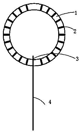
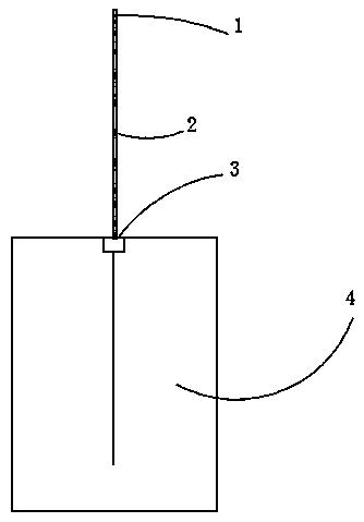
[0027] Present embodiment is a kind of energization to good conductor such as aluminum plate 4, makes such as figure 2 and image 3 The aluminum plate shown has a current flowing through it to generate heat, forming a good conductor heating body (device), which can be used as a heating soleplate of an electric iron, etc.

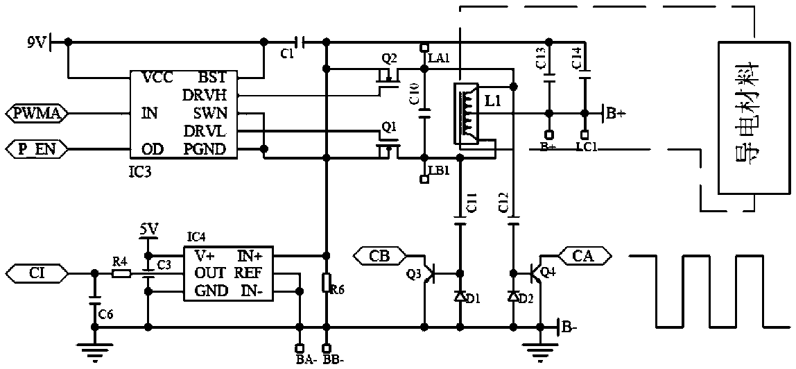
[0028] In this embodiment, in order to apply power to both ends of a good conductor, the following steps are required:

[0029] First, convert the output of the power supply into high-frequency oscillation. This step can add either end of the output end of the power supply to both ends of a coil, and the wire drawn from the middle of the coil is connected to the other end of the power supply to form two loops, and then in each Each controllable switch is set in the circuit. The controllable switch generally uses two MOS tubes, the switch tube Q1 and the switch tube Q2. The two switches are closed in turn, so that the direction of the current in the coil al...


PUM


Abstract

The invention provides an electric heating method and an electric heating driving circuit. The method adopts a good conductor as a heating body, and comprises the steps of converting a power supply into a high-frequency oscillating electric signal, adding the high-frequency oscillating electric signal to the primary side of an isolation transformer, connecting the good-conductor heating body to the secondary side of the isolation transformer, wherein the number of turns of a secondary coil is far less than the number of turns of a primary coil. The heating driving circuit comprises a power supply capable of supplying power to the good conductor. In the invention, the power supply is converted into a high-frequency signal, and then the high-frequency signal is outputted by the secondary soil of the isolation transformer, so that extremely low battery internal resistance is generated, the power supply to the good conductor is realized, the good conductor itself is heated, the heat is directly conducted to the heated material, and the heat efficiency is improved.

Description

technical field [0001] The invention relates to the field of electric heating, in particular to an electric heating method and an electric heating drive circuit which utilize current flowing through a good conductor to generate heat. Background technique [0002] Those skilled in the art know that adding a suitable voltage at both ends of a conductor with a certain resistance, such as a resistance wire, will consume electric energy and generate heat, and the formula J=I 2 Rt=(U 2 / R) t. It means that the heat J is proportional to the square of the voltage U applied to both ends of the heating element such as a resistance wire, and is proportional to the power-on time t and inversely proportional to the resistance R of the resistance wire, or the heat J is proportional to the current I flowing through the heating element such as a resistance wire Proportional to the square of , proportional to the resistance R of the heating element, and proportional to the power-on time t....

Claims


Application Information

Patent Timeline
Patent Type & Authority Applications(China)
IPC IPC(8): H05B3/00H05B6/06H05B6/36H05B6/68
CPCH05B3/0019H05B6/06H05B6/36H05B6/68
Inventor 何永平
Owner 何永平
Why Eureka
Try Eureka