Middle distance flat-plate wireless power transmission system based on magnetic resonance coupling

A technology of wireless power transmission and magnetic resonance coupling, applied in electromagnetic wave systems, electrical components, circuit devices, etc., can solve the problems of large cross-sectional size, unfavorable system circuit module integration, and high processing accuracy requirements

Inactive Publication Date: 2015-06-24
喻易强 +1
View PDF3 Cites 13 Cited by
  • Summary
  • Abstract
  • Description
  • Claims
  • Application Information

AI Technical Summary

Problems solved by technology

However, the currently disclosed wireless energy transmission systems based on magnetic resonance coupling all use circular copper core wire windings to design transceiver coils, which are three-dimensional structures, which not only have large cross-sectional dimensions, are bulky, require high processing accuracy, and are not conducive to system circuits. Module integration, miniaturization, and high processing costs

Method used


Image

  • Middle distance flat-plate wireless power transmission system based on magnetic resonance coupling
  • Middle distance flat-plate wireless power transmission system based on magnetic resonance coupling
  • Middle distance flat-plate wireless power transmission system based on magnetic resonance coupling

Examples


Embodiment 1

[0038] Embodiment 1: A flat-plate magnetic resonance coupling wireless power transmission system using a symmetrical coil structure

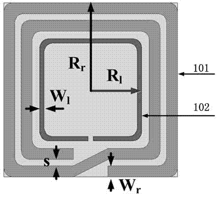
[0039] The front structure diagrams of the transmitter module and the receiver module are as follows: figure 1 and figure 2 As shown, there is no metal sheet attached to the back.

[0040] according to figure 1 and figure 2 The symbol identification in the shown structure diagram, combined with the actual application requirements, the design in this embodiment adopts the following geometric parameters and electrical parameters:

[0041] Table 1 Geometric parameters and electrical parameters of the transmitting module and receiving module in Embodiment 1

[0042] symbol identification

Ranges)

R r

50mm

[0043] R l

25~33(mm)

W r

5.9~6.8(mm)

W l

2.1~2.8(mm)

S

3.2~4.5(mm)

Resonant capacitance value

200~250(pF)

[0044] Such as Figure 8 As shown,...

Embodiment 2

[0047] Embodiment 2: A flat-plate magnetic resonance coupling wireless power transmission system with a parasitic coil structure added

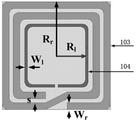
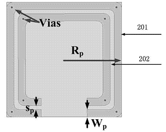
[0048] The front structure diagram of transmission module and load module is as follows: figure 1 As shown, the structure diagram of the back of the transmission module and the load module is as follows figure 2 shown.

[0049] according to figure 1 and figure 2 The symbol identification in the shown structure diagram, combined with the actual application requirements, the design in this embodiment adopts the following geometric parameters and electrical parameters:

[0050] Table 2 Geometric parameters and electrical parameters of the transmitting module and receiving module in Embodiment 2

[0051] symbol identification

Ranges)

R r

50mm

R l

25~33(mm)

W r

5.9~6.8(mm)

W l

2.1~2.8(mm)

S

3.2~4.5(mm)

Resonant capacitance value

200~250(pF)

R p

50mm

...

Embodiment 3

[0056] Embodiment 3: A flat-plate magnetic resonance coupled wireless power transmission system using an asymmetric coil structure

[0057] The front structure diagram of the transmitting module and receiving module is as follows: Figure 5 As shown, the structure diagram on the back is shown in Figure 6 shown.

[0058] according to Figure 5 and Figure 6 The symbol identification in the shown structure diagram, combined with the actual application requirements, the design in this embodiment adopts the following geometric parameters and electrical parameters:

[0059] Table 3 Geometric parameters and electrical parameters of the transmitting module and receiving module in Embodiment 3

[0060] symbol identification

Ranges)

R TXr

100mm

R TXl

43~58(mm)

W TXr

7.1~8.5(mm)

W TXl

3.4~5.0(mm)

S TXr

11.9~14.2(mm)

R RXr

25mm

R RXl

14.2~17(mm)

W RXr

1.7~2.6(mm)

W RXl

0....


PUM


Abstract

The invention provides a middle distance flat-plate wireless power transmission system based on magnetic resonance coupling. A complanation structure is adopted by the wireless power transmission system, and the system can be processed through a plate-making mode of a printed circuit board. Coil coplanar design is further adopted by the system, by placing an exciting coil (102) and a transmitting terminal resonance coil (101) on the same side of a dielectric substrate, meanwhile, by placing a loading coil and a receiving terminal resonance coil on the same side of the dielectric substrate, a bottom layer of the printed circuit board can be used for adding adjustable electronic parts and components, matching a circuit and rectifying a voltage regulator circuit, and the integration level of the system is improved. A parasitism structure is further adopted by the system, by utilizing a parasitic coil to the resonance coils, the coupling intensity among magnetic coupling resonance coils is strengthened, the transmission efficiency is improved, and the transmission distance is increased. The invention further provides a design and application scheme of a point-to-multipoint wireless power transmission system, and the wireless charging and electricity supplying to multiple consumer electronics, communication equipment and LED lighting equipment are achieved simultaneously.

Description

technical field [0001] The invention relates to a mid-distance planar wireless power transmission system based on magnetic resonance coupling, which belongs to the technical field of wireless power transmission. Background technique [0002] With the continuous development of electronics, electrical and automation control technologies, various household appliances and 3C equipment (Computer, Communication equipment and Consumer electronics) have been widely popularized. However, traditional household appliances rely on power cords and power sockets. The wired connection between them is used for power supply, and the emerging 3C devices with built-in batteries also need a wired connection between the charging cable and the power socket for charging, so that the wires that provide power supply for these electronic devices can be seen everywhere. These wires not only occupy our activity space and limit the convenience of equipment use, but also create hidden dangers in the safe...

Claims


Application Information

Patent Timeline
Patent Type & Authority Applications(China)
IPC IPC(8): H02J17/00H02J50/12H02J50/50
Inventor 喻易强法瑞德.朱拉里陈志璋
Owner 喻易强
Why Eureka
Try Eureka