
Surgical tourniquet for hand and foot surgery

A tourniquet and surgical technology, applied in tourniquet and other directions, can solve the problems of poor use effect, inconvenient pulling and contraction force, limb injury, etc., and achieve the effect of prolonging service life, fast hemostasis efficiency, and increasing stability.

Inactive Publication Date: 2019-08-23
李攀
View PDF0 Cites 0 Cited by
  • Summary
  • Abstract
  • Description
  • Claims
  • Application Information

AI Technical Summary

Problems solved by technology

[0004] The purpose of the present invention is to provide a surgical tourniquet for hand and foot surgery, to solve the problem that the existing tourniquet for hand and foot surgery proposed in the background technology has a simple structure, but the operation is cumbersome. It is necessary to align the two ends of the tourniquet, insert one end of the tourniquet into the buckle of the other end and tighten the tourniquet, and use the contraction of the tourniquet to clamp the patient's limbs, so as to achieve the hemostatic effect on the patient's hands and feet and affect the hemostasis In the process of hemostasis, it is not easy to control the strength of pulling and contraction, and it is not easy to judge whether the use of the tourniquet achieves the hemostatic effect. Often, whether the use of the tourniquet achieves the effect is determined by whether the bleeding continues at the damaged part of the limb as a reference. The use effect is poor, and it is easy to cause damage to the patient's limbs due to the large force during the tightening and hemostasis process

Method used


Image

  • Surgical tourniquet for hand and foot surgery
  • Surgical tourniquet for hand and foot surgery
  • Surgical tourniquet for hand and foot surgery

Examples


Embodiment Construction

[0019] The following will clearly and completely describe the technical solutions in the embodiments of the present invention with reference to the accompanying drawings in the embodiments of the present invention. Obviously, the described embodiments are only some, not all, embodiments of the present invention. Based on the embodiments of the present invention, all other embodiments obtained by persons of ordinary skill in the art without making creative efforts belong to the protection scope of the present invention.

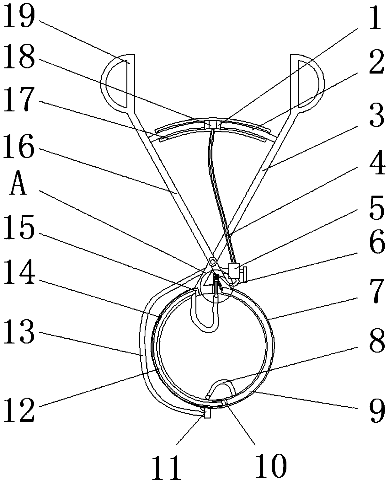
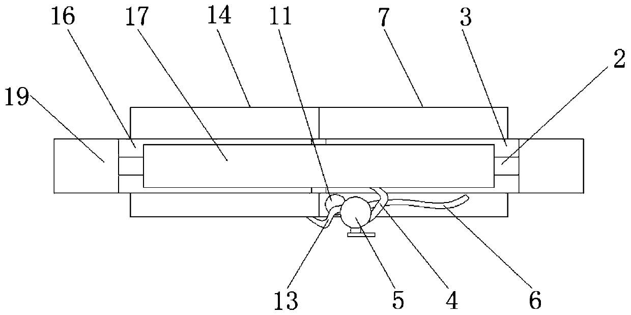
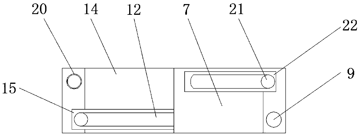
[0020] see Figure 1-4, an embodiment provided by the present invention: a surgical tourniquet for hand and foot surgery, comprising a first fixing rod 3, a second fixing sleeve 7, a tourniquet 8, a first fixing sleeve 14 and a second fixing rod 16, the first Fixed rod 3 is hinged with second fixed rod 16, and the same end of first fixed rod 3 and second fixed rod 16 is respectively provided with first fixed sleeve 14 and second fixed sleeve 7, and first fixed...


PUM


Abstract

The invention discloses a surgical tourniquet for hand and foot surgery. The surgical tourniquet comprises a first fixing rod, a second fixing sleeve, a tourniquet, a first fixing sleeve and a secondfixing rod, wherein the first fixing rod and the second fixing rod are hinged. Through the arrangement of regulating seats on the first fixing sleeve and the second fixing sleeve, the elasticity of atension spring between a sealing sheet and the regulating seat is set to be constant with the pressure required by hemostasis; the tension spring is used for achieving the effect of automatically detecting the hemostasis force intensity; when the extrusion force exerted by the tourniquet on the limbs of a patient reaches the hemostasis effect, the descending is performed in a way of overcoming theelasticity of the tension spring to block the regulating seat; the air circulation between a piston groove and a movable groove is blocked; the moving rod is limited from continuously driving the tourniquet for tightening; the defect that the hemostasis pressure of the existing tourniquet is completely and independently judged by an operator is overcome; the defect of injury on the limbs due to too great hemostasis pressure or hemostasis effect influence due to small hemostasis pressure can be avoided; the hemostasis effect and the use safety performance are improved.

Description

technical field [0001] The invention relates to the technical field of medical instruments, in particular to an operation tourniquet for hand and foot surgery. Background technique [0002] When bleeding is dealt with in a certain way, it is called hemostasis to quickly stop the blood from flowing outward. The effect of hemostasis varies from person to person, some are fast, some are slow, and it is related to platelets. Under normal circumstances, bleeding caused by damage to small blood vessels occurs within a few minutes. This phenomenon is called physiological hemostasis. During the operation, some patients need to suture the blood vessels when their blood vessels rupture. , to avoid the loss of blood caused by blood circulation, which will affect the life safety of patients. [0003] At present, the existing surgical tourniquet for hand and foot surgery is simple in structure, but the operation is relatively cumbersome. After the tourniquet is set on the patient's limb...

Claims


Application Information

Patent Timeline
Patent Type & Authority Applications(China)
IPC IPC(8): A61B17/135
CPCA61B17/1322A61B17/135A61B17/1355
Inventor 李攀马新强杨占华郭海涛孟祥栋
Owner 李攀
Learn More