Blood vessel clamp for vascular surgery
A gripper and blood vessel technology, applied in the field of medical devices, can solve the problems of damaged blood vessels, inconvenient operation, occupation of surgical operation space and uncontrollable clamping force, etc., and achieves the effect of saving operation space, facilitating surgery and clamping blood vessels
- Summary
- Abstract
- Description
- Claims
- Application Information
AI Technical Summary
Problems solved by technology
Method used
Image
Examples
Embodiment 1
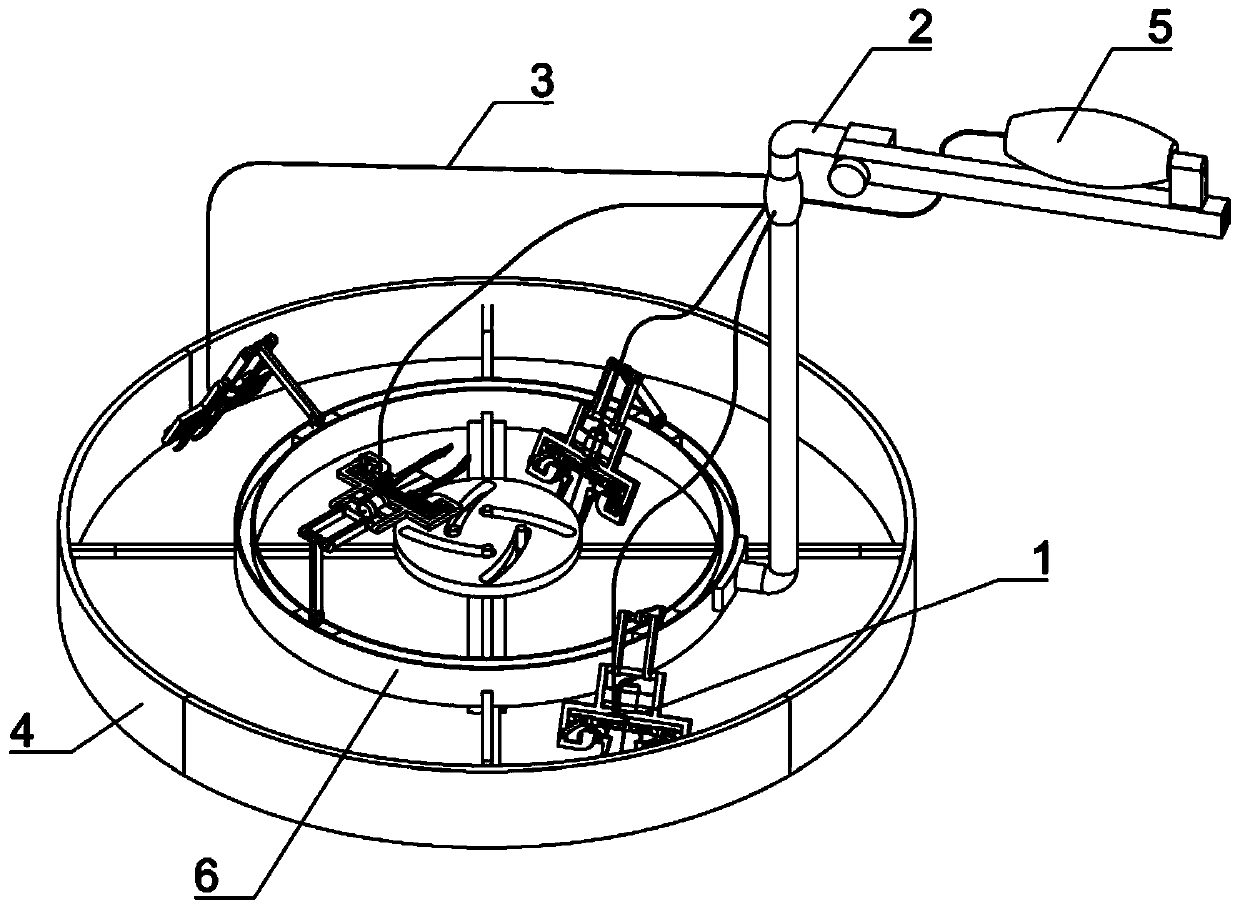
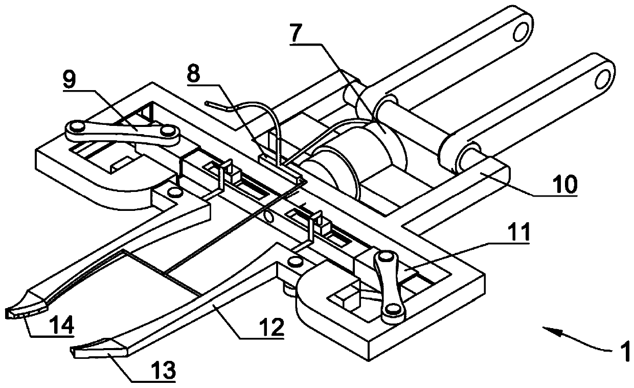
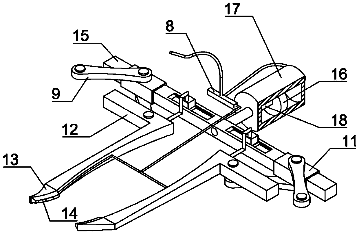
[0037] Embodiment one, by figure 1 , figure 2 , image 3 , Figure 4 and Figure 5 Given, the present invention includes a base 6, a clamping mechanism 1 and a one-way air bag 5, in order to meet the needs of the operation, the clamping mechanism 1 can rotate on the base 6, the clamping mechanism 1 includes a frame body 10, the frame The body 10 is the supporting body of the clamping mechanism 1, the rear end of the frame body 10 is fixed with a pushing mechanism 7, the upper end of the frame body 10 is fixed with a cavity 8, and a sealing plug that can slide in the cavity 8 is provided in the cavity 8 , a tension spring 23 is connected between the right end of the sealing plug and the cavity 8, and the front end of the frame body 10 is provided with two pliers rods 12 that can slide left and right in the frame body 10, and there is a The cross bar 15 that can slide back and forth in the frame body 10 is set with two sleeves 11 that can slide left and right on the cross b...
Embodiment 2
[0039]Embodiment two, on the basis of embodiment one, by Figure 4 Given, in order to realize that the gas in the one-way airbag 5 can enter the pushing mechanism 7 through the cavity 8, the sealing plug includes a first sealing block 22 and a second sealing block 20, and the first sealing block 22 and the second sealing block 20 are connected by a fixed rod 21, and the connection between the one-way airbag 5 and the push mechanism 7 on the cavity 8 is between the first sealing block 22 and the second sealing block 20. When the gas enters the cavity 8, due to There is a sealed structure between the first sealing block 22 and the second sealing block 20, so the gas can only enter the pushing mechanism 7 through the conduit 3. It should be noted that the left end of the second sealing block 20 communicates with the outside atmosphere;
[0040] Because the vascular tolerance of different patients is different, the cavity 8 is a transparent structure, and the outer wall of the cav...
Embodiment 3
[0041] Embodiment three, on the basis of embodiment one, by figure 2 , Image 6 and Figure 7 Given, in order to avoid pinching the blood vessels, each of the forceps rod 12 and the forceps head 13 is a cavity structure, and the cavity in the forceps rod 12 communicates with the cavity in the forceps head 13 through a liquid outlet pipe 29 , the outer end of the liquid outlet pipe 29 runs through the pincer head 13, and a first piston 28 that can slide back and forth in the pincer bar 12 is provided in each pincer bar 12, and the rear end of the first piston 28 is fixedly connected with a The first piston rod 27 sliding in the pincer rod 12;
[0042] In order to prevent the patient's blood vessel from being pinched while clamping the patient's blood vessel, the upper end of the cross bar 15 is provided with two chute 25, the chute 25 corresponds to the pincer rod 12 one by one, and each chute 25 is provided with a The slider 26 that can slide left and right in the chute 25...
PUM
 Abstract
Description
Claims
Application Information
 - R&D
- Intellectual Property
- Life Sciences
- Materials
- Tech Scout
- Unparalleled Data Quality
- Higher Quality Content
- 60% Fewer Hallucinations
Browse by: Latest US Patents, China's latest patents, Technical Efficacy Thesaurus, Application Domain, Technology Topic, Popular Technical Reports.
© 2025 PatSnap. All rights reserved.Legal|Privacy policy|Modern Slavery Act Transparency Statement|Sitemap|About US| Contact US: help@patsnap.com


