Clamp spring automatic assembly device

An automatic and circlip technology, used in assembly machines, metal processing, metal processing equipment, etc., can solve the problems of low assembly efficiency, labor consumption, and troublesome circlip assembly, and achieve the effect of improving production efficiency and reducing labor costs.

Pending Publication Date: 2019-08-23
HENGDIAN GRP INNUOVO ELECTRIC
View PDF0 Cites 9 Cited by
  • Summary
  • Abstract
  • Description
  • Claims
  • Application Information

AI Technical Summary

Problems solved by technology

The assembly of the circlip is very troublesome, l

Method used


Image

  • Clamp spring automatic assembly device
  • Clamp spring automatic assembly device
  • Clamp spring automatic assembly device

Examples


Embodiment Construction

[0018] The present invention will be further described below according to the accompanying drawings and specific embodiments.

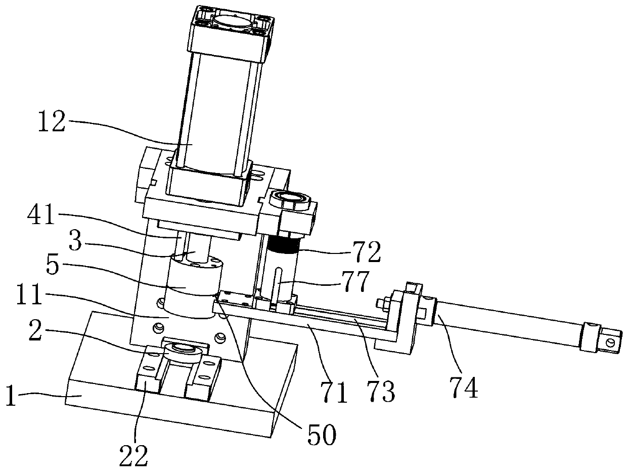
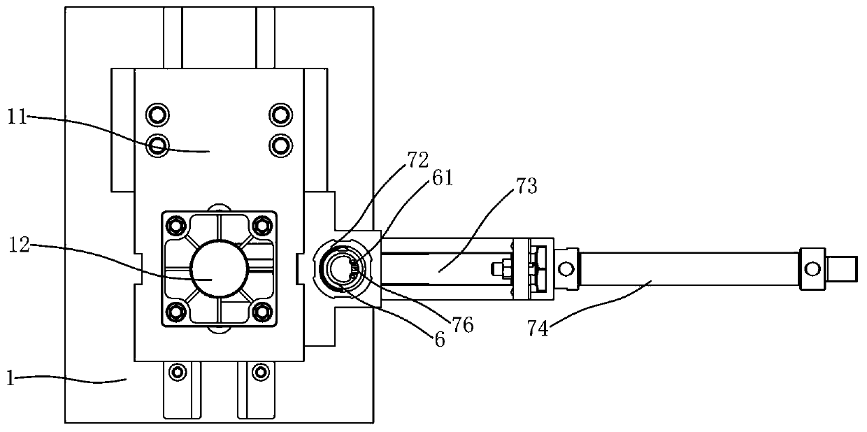
[0019] Depend on Figure 1 to Figure 3 As shown, an automatic clip spring device of the present invention includes a base plate 1, on which a press 12 is fixed through a bracket 11, and an end cover positioning seat is provided on the base plate 1, and the end cover 2 of this embodiment has two axial sides Even annular protrusion 21, the end cover positioning seat of this embodiment is made up of slide rails 22 oppositely arranged on the left and right, end cover 2 is placed between the two slide rails, and end cover 2 is pushed into the lower side of the press by sliding. Wherein, the end cap 2 has an end cap inner hole 23 axially penetrating, and an annular groove 24 is formed on the wall of the end cap inner hole 23

[0020] The press 12 includes a pressure head assembly, the pressure head assembly includes a pressure rod 3, a guide block 4, and a...


PUM


Abstract

The invention aims to provide a clamp spring automatic assembly device which can realize automatic assembly of a clamp spring so as to improve the production efficiency and reduce the labor cost. In order to achieve the aim, the invention adopts the following technical scheme that the clamp spring automatic assembly device comprises a bottom plate, a press is fixed on the bottom plate through a support, and an end cover positioning base is arranged on the bottom plate; the press comprises a press head assembly, the press head assembly comprises a pressing rod, a guide block and a positioning block, wherein the guide block is arranged on the pressing rods in a sleeve mode, a plurality of vertically-penetrating guide holes are formed in the guide block, the lower ends of guide columns penetrate through the guide holes to be fixed with the positioning block, and the positioning block is arranged on the circumferential outer side of the pressing rod in a sleeve mode and is provided with apressing groove which penetrates vertically; and a feeding port allowing the clamp spring to pass is formed in the side face of the positioning block, the feeding port communicates with the pressing groove, the pressing groove comprises an upper pressing groove section and a lower pressing groove section, and the inner diameter of the lower pressing groove section is gradually reduced from top tobottom.

Description

technical field [0001] The invention relates to an automatic clip spring device. Background technique [0002] A circlip is a fixture commonly used on a shaft or in a hole to limit the axial movement of parts on the shaft or in the hole. The circlip includes an arc-shaped elastic bending part and a circlip protrusion at the end of the elastic bending part. The circlip protrusion has a small hole for matching with the tip of the needle-nose pliers or the circlip pliers. [0003] In the prior art, in order to place the circlip in the end cap, the assembler needs to clamp the circlip through needle-nose pliers or circlip pliers and deform the circlip, put the circlip into the annular groove of the inner hole of the end cap and then Loosen the needle nose pliers or snap ring pliers. The assembly of the snap ring is very troublesome, labor-intensive, and the assembly efficiency is low. Contents of the invention [0004] The object of the present invention is to provide an au...

Claims


Application Information

Patent Timeline
IPC IPC(8): B23P19/02B23P19/00
CPCB23P19/02B23P19/001B23P21/002B23P19/10
Inventor 胡校铭黄亮
Owner HENGDIAN GRP INNUOVO ELECTRIC
Why Eureka
Try Eureka