Welding method for tube sheet of robot based on laser three-dimensional modeling

A laser three-dimensional, tube-sheet welding technology, applied in the direction of manipulators, program-controlled manipulators, manufacturing tools, etc., can solve problems such as failure to meet user requirements, poor consistency of heat dissipation pipes, and welding defects

Inactive Publication Date: 2019-08-23
成都卡诺普机器人技术股份有限公司
View PDF6 Cites 5 Cited by
  • Summary
  • Abstract
  • Description
  • Claims
  • Application Information

AI Technical Summary

Problems solved by technology

The traditional vision-based tube plate welding method is mainly based on a template tube plate, and then the robot is taught to make a fixed offset. When the position of the heat pipe is irregular,

Method used


Image

  • Welding method for tube sheet of robot based on laser three-dimensional modeling
  • Welding method for tube sheet of robot based on laser three-dimensional modeling
  • Welding method for tube sheet of robot based on laser three-dimensional modeling

Examples


Embodiment Construction

[0023] In order to enable those skilled in the art to better understand the technical solutions of the present invention, the present invention will be further described in detail below in conjunction with specific embodiments.

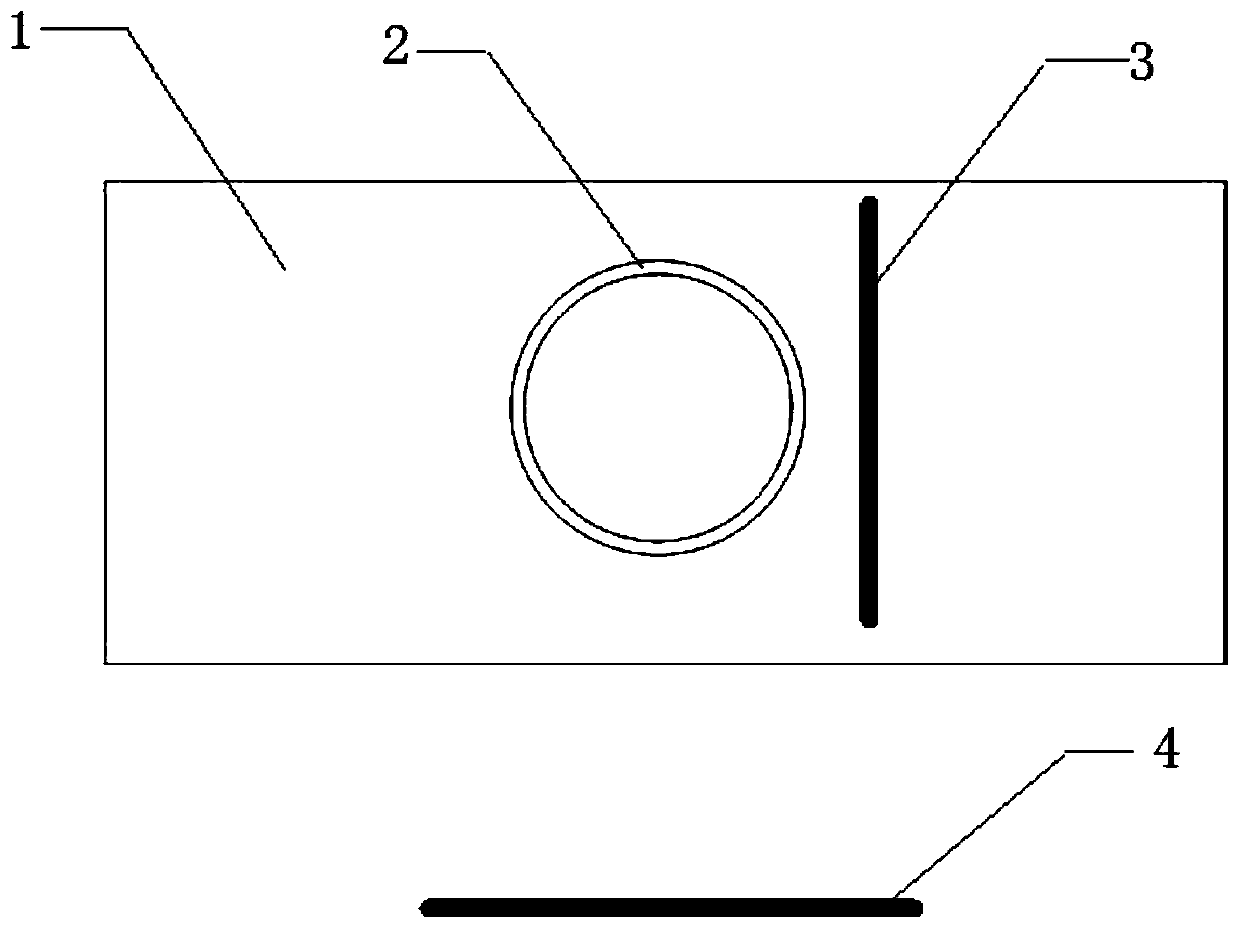
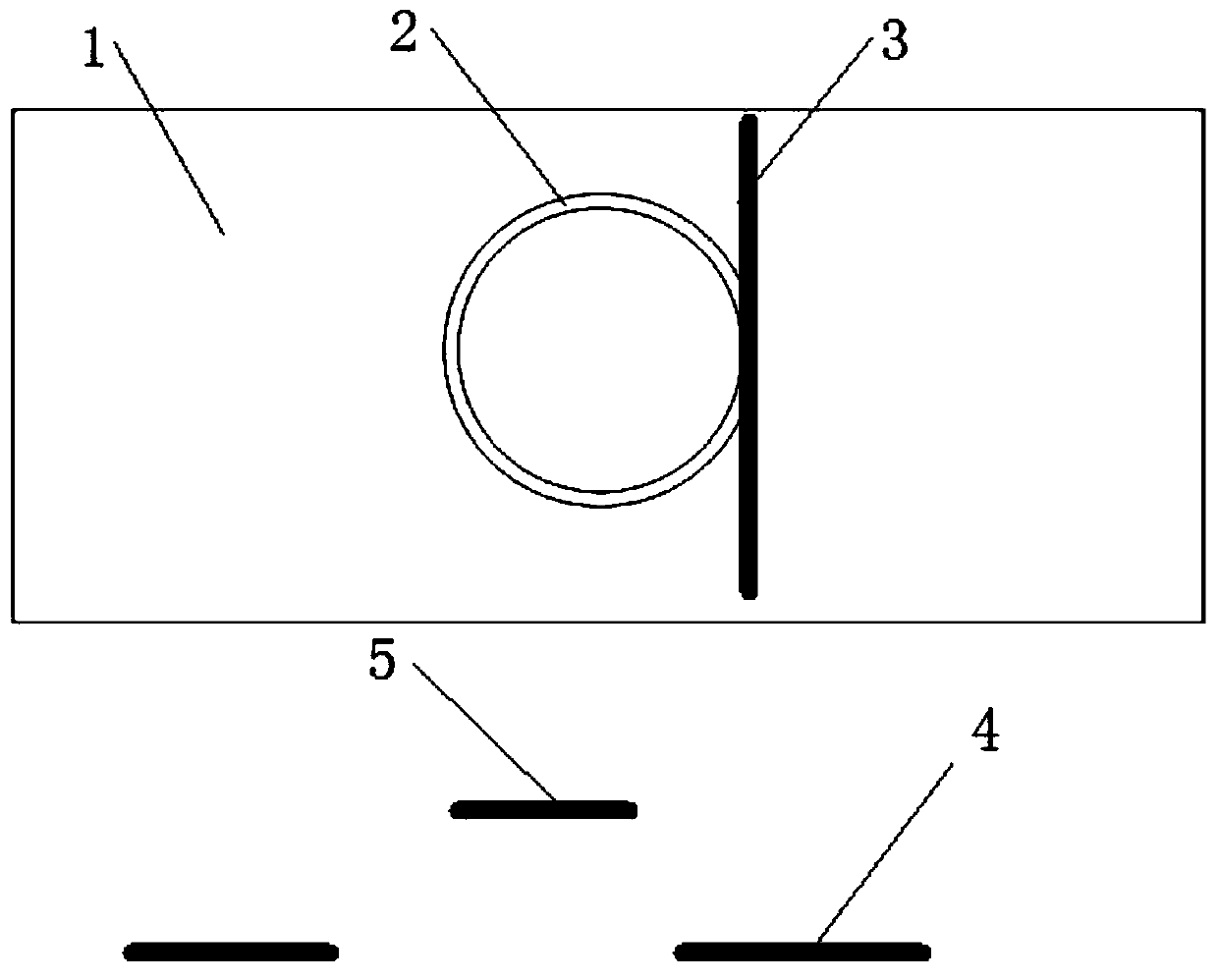
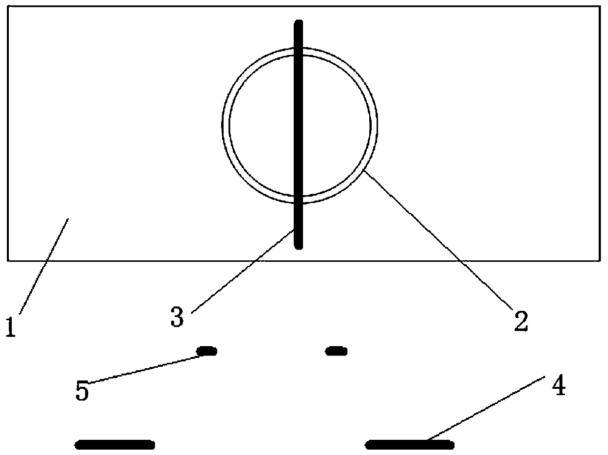
[0024] The tube plate to be welded in the present invention includes a base plate 1 and a heat dissipation pipe 2, the base plate has a through hole, and the heat dissipation pipe 2 is inserted into the through hole. During welding, it is necessary to weld the edge of the through hole on the upper surface of the substrate 1 with the heat dissipation pipe 2 .

[0025] The present invention comprises the following steps:

[0026] Step A. Three-dimensional imaging of the tube sheet to be welded.

[0027] First fix the tube sheet on the workbench, then use the laser probe fixed on the welding robot to scan the set area on the tube sheet row by row or column by row and sample the scanned image, and combine the current coordinate position of the welding ro...


PUM


Abstract

The invention discloses a welding method for a tube sheet of a robot based on laser three-dimensional modeling. The welding method is characterized by comprising the following steps: A, carrying out three-dimensional imaging on a tube sheet needed to be welded; B, recognizing a three-dimensional contour of a weld joint of the tube sheet by datamation of three-dimensional imaging; and C, inputtingthe three-dimensional contour of the weld joint to a welding robot for welding through a control command. The welding method with the steps overcomes difficulties in actual production, for example, deformation of a heat-dissipating tube of a heat-dissipating tube sheet, inconsistent mounting angle and mounting height of the heat-dissipating tube, placing deviation of the heat-dissipating tube sheet and the like. Meanwhile, the welding defect caused by difference between the heat-dissipating tube and a template in welding by way of the template is overcome.

Description

technical field [0001] The invention relates to a method for welding tube sheets by using a welding robot. Background technique [0002] The heat dissipation tube plate is a heat dissipation device, and its structure is to vertically fix several heat dissipation pipes on a flat plate. In order to improve production efficiency and reduce the labor intensity of workers, most welding robots are now used to weld heat pipes and plates. The traditional vision-based tube plate welding method is mainly based on a template tube plate, and then the robot is taught to make a fixed offset. When the position of the heat pipe is irregular, thermal deformation occurs when the heat pipe plate is welded, and the consistency of the heat pipe is relatively poor. When poor, it is easy to produce welding defects. Can not meet the user's requirements. Contents of the invention [0003] In view of this, the present invention provides a robot tube-sheet welding method based on laser three-dime...

Claims


Application Information

Patent Timeline
IPC IPC(8): B25J9/16B25J11/00
CPCB25J9/1605B25J11/005
Inventor 张成军
Owner 成都卡诺普机器人技术股份有限公司
Why Eureka
Try Eureka