
Foundation pit soil moving-out device

A technology for foundation pits and installation gaps, which is applied in foundation structure engineering, earth movers/excavators, excavation, etc., and can solve problems such as occupying tower cranes

Inactive Publication Date: 2019-08-23
CHONGQING CONSTR ENG SECOND CONSTR CO LTD
View PDF6 Cites 2 Cited by
  • Summary
  • Abstract
  • Description
  • Claims
  • Application Information

AI Technical Summary

Problems solved by technology

[0003] The purpose of the present invention is to provide a foundation pit excavation device to solve the current problem that a tower crane is required for the excavation of foundation pit slope road excavation

Method used


Image

  • Foundation pit soil moving-out device
  • Foundation pit soil moving-out device
  • Foundation pit soil moving-out device

Examples


Embodiment 1

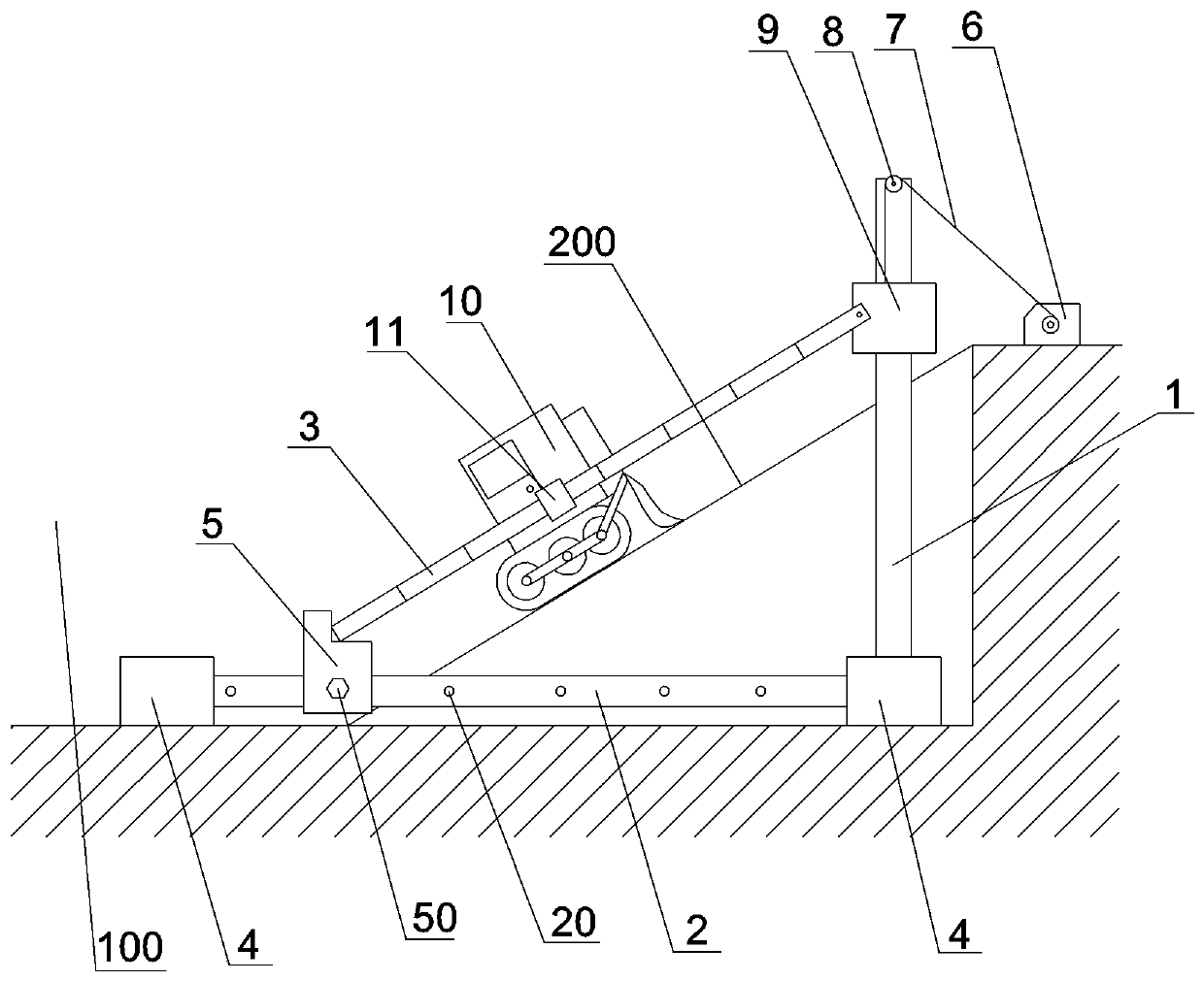
[0030] like image 3 As shown, the foundation pit excavation device of this embodiment includes an excavation mechanism arranged above the foundation pit ramp 200 and two support and guide mechanisms respectively arranged on both sides of the foundation pit ramp 200 .

[0031] The support guide mechanism comprises a vertical support rod 1, a horizontal support rod 2 and an inclined guide rod 3, and the horizontal support rod 2 is fixed on the side bottom of the foundation pit ramp 200 by two fixed piles 4 inserted into the bottom of the foundation pit 100, vertically The bottom of the support rod 1 is fixed on the fixed pile 4 close to the wall of the foundation pit, and the vertical support rod 1 is located at the top side of the foundation pit ramp 200 . The inclined guide rod 3 is parallel to the upper surface of the foundation pit ramp 200, and the vertical support rod 1 is slidably connected with a moving sleeve 9, and the moving sleeve 9 and the top of the inclined guide...

Embodiment 2

[0039] The difference between this embodiment and Embodiment 1 is that the splicing method of the segments is plug-in, that is, the end face of one segment is fixed with an insertion rod, and the end face of the other segment is fixed with a socket, and the insertion rod is inserted into the socket , to achieve splicing of adjacent segments.

Embodiment 3

[0041] The difference between this embodiment and the first embodiment is that the bulldozer is also equipped with a rake tine type soil loosening part, which is rotatably connected to the bulldozer, and the locking between the soil loosening part and the bulldozer is realized through buckles. When the bulldozer walks down along the inclined guide bar 3, the loosening parts are put down, and the loosening parts loosen the soil on the slope; Loose soil for bulldozing.


PUM


Abstract

The invention belongs to the field of building construction, and particularly discloses a foundation pit soil moving-out device. The foundation pit soil moving-out device comprises supporting and guiding mechanisms arranged on the side edges of a foundation pit ramp and a soil moving-out mechanism arranged on the foundation pit ramp; each supporting and guiding mechanism comprises a vertical supporting rod, a horizontal supporting rod and an inclined guide rod; each vertical supporting rod is fixed at the side edge of the top end of the foundation pit ramp; each horizontal supporting rod is fixed at the bottom of the side edge of the foundation pit ramp; each inclined guide rod is parallel to the upper surface of the foundation pit ramp; the top end of each inclined guiding rod is slidingly connected to the corresponding vertical supporting rod; each inclined guide rod is formed by splicing a plurality of segments; a segment installation gap is formed between the bottom end of each inclined guide rod and the corresponding horizontal supporting rod; and each horizontal supporting rod is slidingly connected with a segment supporting part capable of filling the corresponding segment installation gap. The soil moving-out mechanism comprises a trolley which is slidingly connected to the inclined guide rods; and a soil bulldozing part is arranged on the trolley. The special soil moving-out device is designed for ramp soil of a foundation pit, and a tower crane is not occupied when the ramp soil of the foundation pit is moved out.

Description

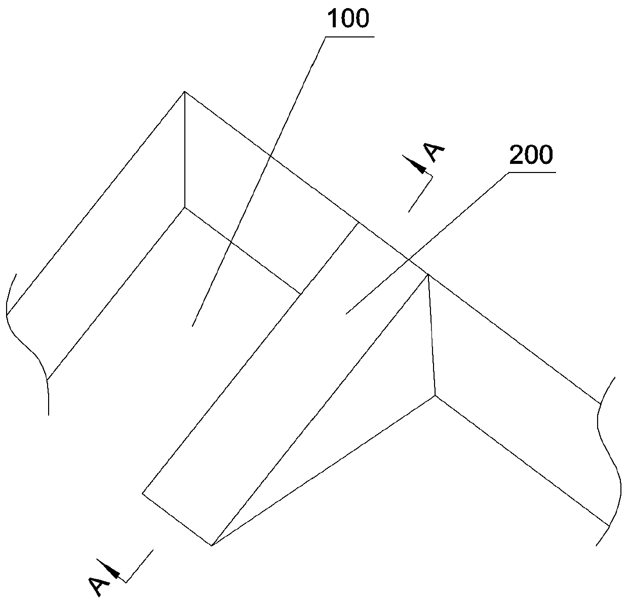
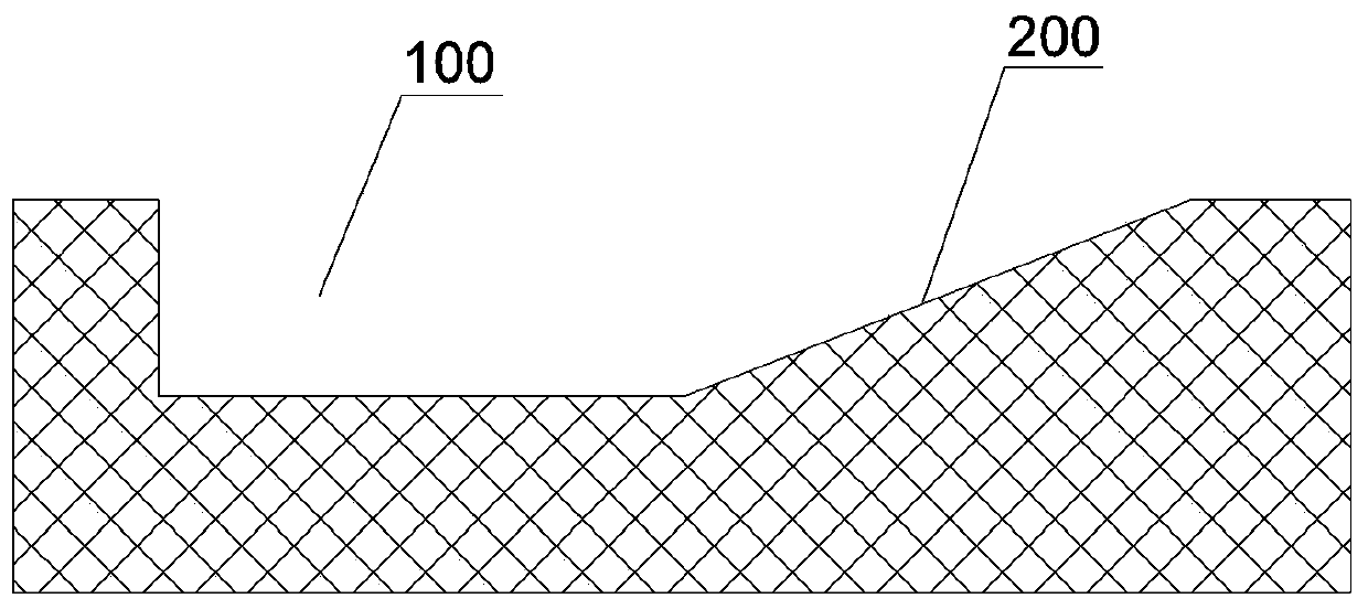
technical field [0001] The invention relates to the technical field of building construction, in particular to an excavation device for a foundation pit. Background technique [0002] as attached figure 1 and 2 As shown, after the foundation pit 100 is excavated and during the foundation pit 100 support construction, it is usually necessary to leave a slope extending from the base to the outside of the foundation pit in the foundation pit 100 as a road for each construction machine tool and excavating machine to enter and exit the foundation pit, and finally The soil of this part of the slope road (that is, the slope of the foundation pit 200) is usually excavated by a tower crane. There are two problems. The storage basket is used to realize the excavation of the road soil on the slope of the foundation pit. However, due to the limited space of the storage basket in this way, the soil loaded is limited, and the tower crane can lift less soil at one time. For a long time,...

Claims


Application Information

Patent Timeline
Patent Type & Authority Applications(China)
IPC IPC(8): E02F3/76E02D17/02E04G27/00
CPCE02D17/02E02F3/7609E04G27/00
Inventor 杨永峰叶腾茂文六智
Owner CHONGQING CONSTR ENG SECOND CONSTR CO LTD
Learn More