Buffer sleeve and working cylinder of hydraulic device using buffer sleeve

A technology of hydraulic devices and buffer sleeves, applied in fluid pressure actuators, mechanical equipment, etc., can solve problems such as insufficient oil supply to the piston chamber, insufficient starting force of piston 2, unstable closing time, etc., to improve the starting force , Increase movement speed, increase the effect of starting speed

Active Publication Date: 2019-08-23
PINGGAO GRP +1
View PDF8 Cites 1 Cited by
  • Summary
  • Abstract
  • Description
  • Claims
  • Application Information

AI Technical Summary

Problems solved by technology

[0004] The above-mentioned working cylinder has the following problems: when the switch is closed, when the buffer sleeve 3 moves the stroke of L2, when the piston 2 has not yet completed the stroke of L1, because the oil hole 5 of the buffer sleeve 3 and the gap between the buffer sleeve 3 and the piston 2 The cross-sectional area of ​​the gap is much smaller than the ring area of ​​the piston 2, resulting in insufficient oil supply in the piston chamber, insufficient starting force of the piston 2, and the "crawling" phenomenon of the piston 2, which in turn leads to longer closing time or unstable closing time

Method used


Image

  • Buffer sleeve and working cylinder of hydraulic device using buffer sleeve
  • Buffer sleeve and working cylinder of hydraulic device using buffer sleeve
  • Buffer sleeve and working cylinder of hydraulic device using buffer sleeve

Examples


Embodiment Construction

[0041] Embodiments of the present invention will be further described below in conjunction with the accompanying drawings.

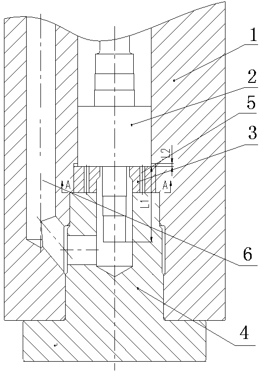
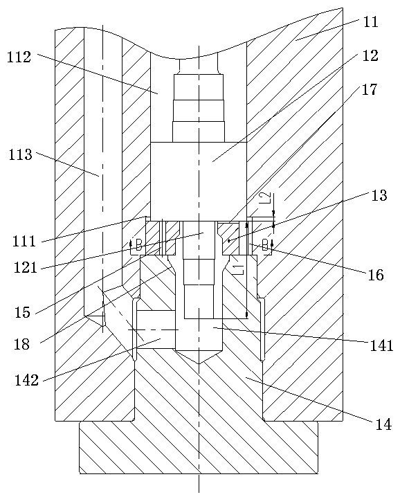
[0042] An embodiment of the working cylinder of the hydraulic device of the present invention, such as image 3As shown, the working cylinder of the hydraulic device includes a cylinder body 11 and a piston 12. The cylinder body 11 is provided with a piston chamber 112. The piston 12 is movably assembled in the piston chamber 112 along the axial direction of the cylinder body 11. The piston chamber 112 is used to communicate with the piston. The inner wall of one end corresponding to the buffer stroke end of 12 is provided with a stop step 111, and the end of this end is provided with a plug 14, and the plug 14 is connected with the cylinder body 11 by bolts. A center hole 141 for inserting the buffer shaft 121 of the piston 12 is provided at the center of the plug 14 .

[0043] The working cylinder of the hydraulic device also includes a buffer sleeve ...


PUM


Abstract

The invention relates to a buffer sleeve and a working cylinder of a hydraulic device using the buffer sleeve. The buffer sleeve is arranged between a stopping step and a plugging head of the workingcylinder of the hydraulic device, and an inner hole allowing a buffer shaft of a piston to be inserted is formed in the buffer sleeve. Oil passing grooves are formed in the end surface of the end, faraway from the plugging head, of the buffer sleeve, and the oil passing grooves communicate with the inner hole of the buffer sleeve. According to the buffer sleeve and the working cylinder of the hydraulic device using the buffer sleeve, due to the fact that the buffer sleeve is arranged between the stopping step and the plugging head of the working cylinder of the hydraulic device, when the working cylinder of the hydraulic device is started, oil can enter the oil passing grooves through gaps between the piston and the inner hole of the buffer sleeve, and the oil entering the oil passing grooves has a driving effect on the piston. Compared with the prior art, the action area of initial oil on the piston is expanded, so that the moving speed of the piston can be increased, thus improvingthe starting force of the working cylinder of the hydraulic device so as to achieve the effect of improving the starting speed of the working cylinder of the hydraulic device.

Description

technical field [0001] The invention relates to a buffer sleeve and a working cylinder of a hydraulic device using the buffer sleeve. Background technique [0002] The hydraulic operating mechanism uses the incompressible principle of liquid to send high-pressure oil to both sides of the working cylinder to realize the opening and closing of the circuit breaker, such as the hydraulic operating mechanism of the circuit breaker disclosed in the invention patent application with the publication number CN101527206A. [0003] Such as figure 1 and figure 2 As shown, the working cylinder of the hydraulic operating mechanism in the prior art includes a cylinder body 1, a piston 2 that is guided and moved in the piston chamber of the cylinder body 1, a plug 4 that is blocked at one end of the piston chamber, and moves axially Buffer sleeve 3 assembled in the piston cavity. The working process of the working cylinder when the hydraulic operating mechanism is closed and started is:...

Claims


Application Information

Patent Timeline
Patent Type & Authority Applications(China)
IPC IPC(8): F15B15/22
CPCF15B15/221F15B2215/30
Inventor 李海文胡月萍刘煜雷琴刘宇杨晓威逯丹
Owner PINGGAO GRP
Why Eureka
Try Eureka