
Power transmission apparatus

A technology of power transmission device and gear, which is applied in the direction of power device, electric power device, transmission device, etc.

Active Publication Date: 2019-08-23
HONDA MOTOR CO LTD
View PDF7 Cites 2 Cited by
  • Summary
  • Abstract
  • Description
  • Claims
  • Application Information

AI Technical Summary

Problems solved by technology

[0003] However, in the device described in Patent Document 1, the gear storage part and the storage part are partitioned by the partition part inside the case, so the size of the device is increased.

Method used


Image

  • Power transmission apparatus
  • Power transmission apparatus
  • Power transmission apparatus

Examples


Embodiment Construction

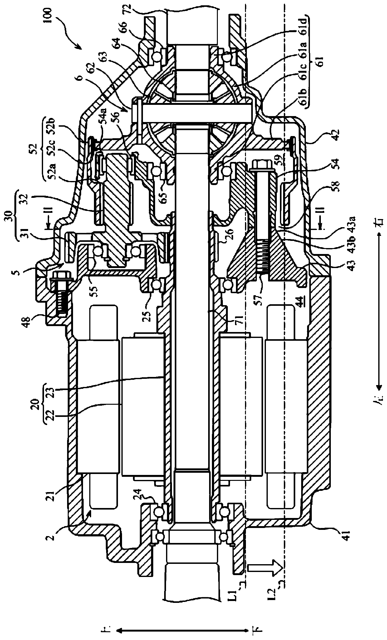
[0014] Below, refer to Figure 1 to Figure 6 One embodiment of the present invention will be described. The power transmission device 100 according to one embodiment of the present invention is a device using the electric motor 2 as a driving source of the vehicle, and is installed in an electric vehicle such as an electric vehicle or a hybrid vehicle.

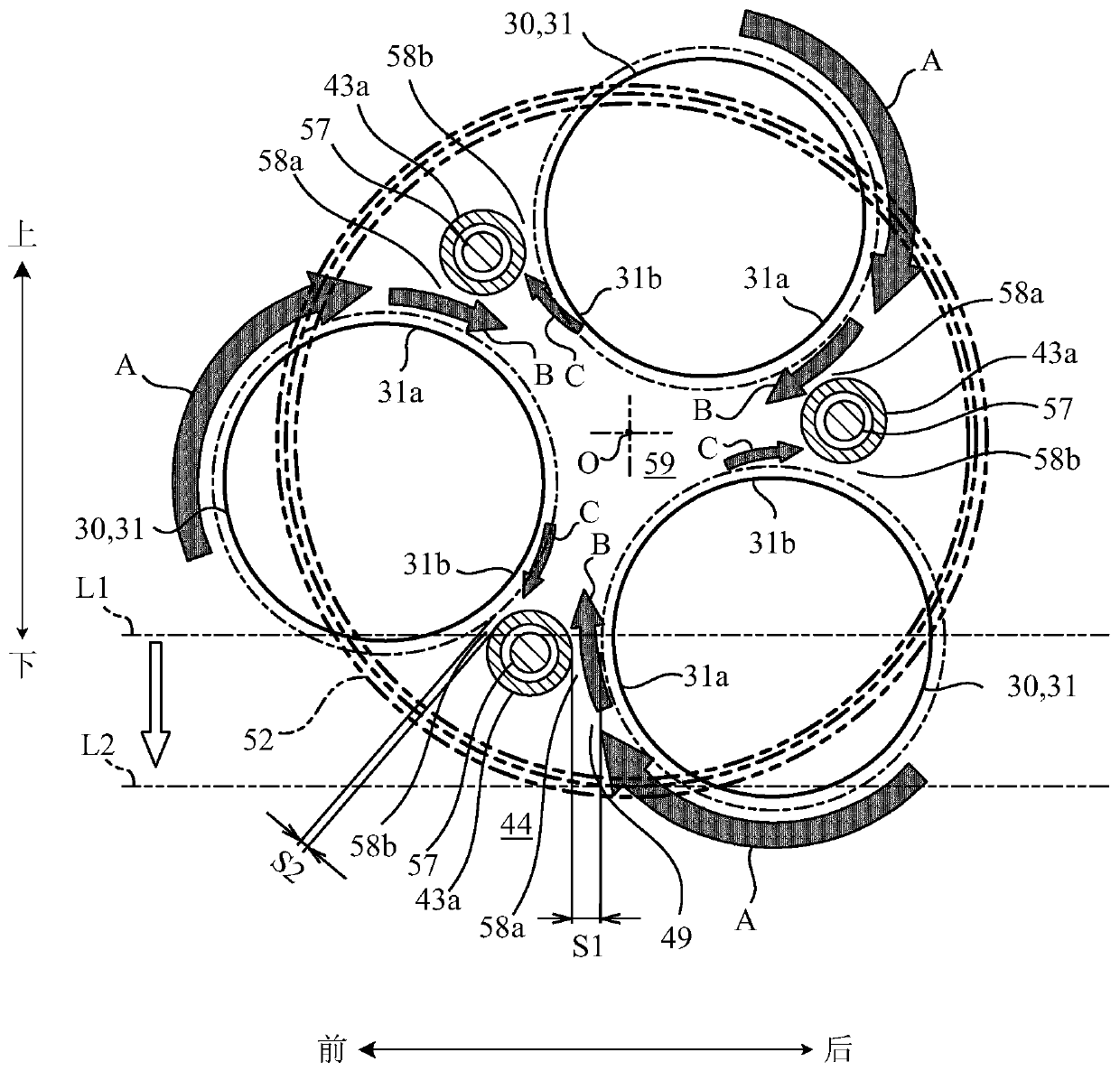
[0015] figure 1 is a sectional view showing a power transmission device according to an embodiment of the present invention, figure 2 is along figure 1 Sectional view of line II-II. In the following, for convenience, the up-down direction, the left-right direction, and the front-rear direction are defined as shown in the figure, and the configuration of each part will be described.

[0016] First, the structure of the power transmission device 100 will be described. The electric motor 2 , the reduction gear train 5 , and the differential mechanism 6 are housed inside the casings 41 and 42 of the power transmission device...


PUM


Abstract

A power transmission apparatus (100) is provided, including: a case (41, 42) having a first oil storage (44) configured to store oil at a bottom thereof; a rotating body rotatably housed in the case (41, 42) and having a second oil storage (59) configured as an approximately cylindrical rotating body for transmitting power and configured to store oil therein; and an introducing portion (58) configured to introduce oil from the first oil storage (44) into the second oil storage (59).

Description

technical field [0001] The invention relates to a power transmission device which transmits power by using a rotating body rotating inside a casing. Background technique [0002] A device for lubricating with oil splashed by gears is conventionally known. Such a device is described in Patent Document 1, for example. The device described in Patent Document 1 includes a storage section for storing lubricating oil in a housing, a gear storage section for storing gears, and a partition section for partitioning the storage section and the gear storage section. In this device, the oil splashed by the gears is stored in the reservoir and the oil level in the gear housing is lowered, thereby reducing the stirring resistance due to the gears. [0003] However, in the device described in Patent Document 1, the gear storage part and the storage part are partitioned by the partition part inside the casing, so the size of the device is increased. [0004] prior art literature [0005...

Claims


Application Information

Patent Timeline
Patent Type & Authority Applications(China)
IPC IPC(8): F16H57/04F16H57/02F16H37/08H02K7/116
CPCF16H37/0826F16H57/02F16H57/042F16H57/0452H02K7/116B60K1/00B60K2001/001B60K2001/006F16H57/0423F16H57/0457F16H57/0476F16H57/0483F16H57/0486F16H1/28F16H37/0813F16H48/08
Inventor 小野光司木藤亮
Owner HONDA MOTOR CO LTD
Features
  • Generate Ideas
  • Intellectual Property
  • Life Sciences
  • Materials
  • Tech Scout
  • Unparalleled Data Quality
  • Higher Quality Content
  • 60% Fewer Hallucinations
Learn More