Confluence gating device

A gating and converging fluid technology, applied in multi-way valves, engine components, mechanical equipment, etc., can solve the problems of liquid flow passage leakage, plastic aging, and the flatness of the contact surface cannot be well guaranteed. To achieve the effect of reliable end face sealing, ensuring flatness and reliable sealing connection

Pending Publication Date: 2019-08-23
爱达普科技(张家港)有限公司
View PDF0 Cites 0 Cited by
  • Summary
  • Abstract
  • Description
  • Claims
  • Application Information

AI Technical Summary

Problems solved by technology

In the actual application process, the said collecting body and the liquid flow selection cover are usually plastic parts. Due to the limitation of the injection molding process, the flatness of the contact surface between the collecting body and the liquid flow selection cover is not very good. Guarantee, coupled with long-term use of plastics will age and the impact of ambient temperature on plastic parts is also greater, so in the actual use process, liquid leakage often occurs at the connection between the liquid flow channel and the liquid inlet and outlet. Affect the normal use of the entire bus gate

Method used


Image

  • Confluence gating device
  • Confluence gating device

Examples


Embodiment Construction

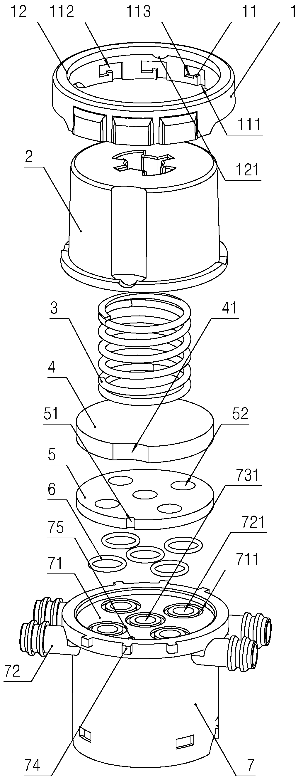
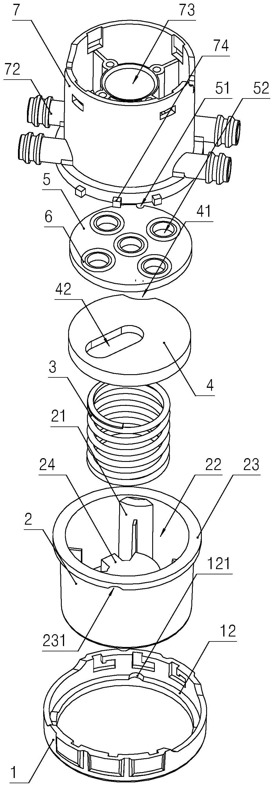
[0017] Attached below Figures 1 to 2 , which describes in detail a specific implementation of a bus gate in the present invention.

[0018] like figure 1 and figure 2 As shown, the confluence gating device of the present invention includes: a confluence body 7, a disk-shaped sealed static plate 5 and a sealed moving plate 4, and a liquid flow selection cover 2 matched with the sealed moving plate 4 and as an elastic The pressing spring 3 of the pressing part, the said confluence body 7 is provided with a liquid outlet channel 73 and four liquid inlet channels communicated one by one with the corresponding liquid inlet pipe 72 (belonging to the common technology in the art, Fig. not shown in), the said confluence body 7 is provided with a static disc installation chamber 71 matching with the said sealed static disc 5, and the bottom wall of the static disc installation chamber 71 is provided with a liquid outlet channel The liquid outlet 731 communicated with 73 and the li...


PUM


Abstract

The invention discloses a confluence gating device. The confluence gating device can form a reliable sealing connection between a liquid flow passage and an inflowing liquid exit and an outflowing liquid entrance, and comprises a confluence body and a liquid flow selection cover, wherein a sealing static disc, a liquid outlet channel and at least two liquid inlet channels are arranged in the confluence body; liquid flow through holes which are in one-to-one correspondence with the liquid outlet channel and the liquid inlet channels are formed in the sealing static disc, and sealing rings whichare in one-to-one correspondence with the inflowing liquid exist and the outflowing liquid entrance are arranged between the confluence body and the sealing static disc; and a sealing movable disc and an elastic pressing part are arranged in the liquid flow selection cover, the liquid flow passage which is arranged in the radial direction is formed in the sealing movable disc, a movable connection locking mechanism is arranged between the liquid flow selection cover and the confluence body, so that the liquid flow selection cover can rotate relative to the confluence body, and can be locked on the confluence body. The confluence gating device is quite wide in application.

Description

technical field [0001] The invention relates to a confluence gating device which can arbitrarily select a plurality of liquid inlet channels to communicate with the liquid outlet channels. Background technique [0002] At present, the traditional confluence gate has a relatively simple structure, and usually includes: a confluence body and a liquid flow selection cover movably connected with the confluence body. A liquid outlet that communicates with the liquid outlet channel and a liquid inlet outlet that communicates with the liquid inlet channel one by one are opened, wherein the liquid outlet inlet is located at the center of the bottom wall of the installation cavity, and the liquid inlet outlet surrounds the The liquid outlet inlet is arranged circumferentially, and the liquid flow selection cover is provided with a radially arranged liquid flow channel that can connect the liquid inlet channel with the liquid outlet channel. In the actual application process, the sai...

Claims


Application Information

Patent Timeline
Patent Type & Authority Applications(China)
IPC IPC(8): F16K11/074
CPCF16K11/074
Inventor 钱金龙杨洪才
Owner 爱达普科技(张家港)有限公司
Why Eureka
Try Eureka