A phase change heat extraction system

A thermal system and phase change technology, applied in lighting and heating equipment, cooling/heating devices for lighting devices, refrigerators, etc. Power supply damage and other problems, to ensure the heat dissipation performance, good heat dissipation effect, and reduce power consumption

Active Publication Date: 2021-02-26
MIANYANG TIANHE MACHINERY MFG
View PDF6 Cites 0 Cited by
  • Summary
  • Abstract
  • Description
  • Claims
  • Application Information

AI Technical Summary

Problems solved by technology

Although the above two heat dissipation methods do not consume additional cooling power, the disadvantages are: the minimum temperature of the LED chip is always higher than the ambient temperature, and often cannot reach the optimum working temperature. The method is also not suitable for ultra-high-power LED lighting lamps, which cannot achieve the proper heat dissipation effect and shorten the service life and lighting effect of LEDs.
And the leakage of water will cause fatal damage to components such as LED chips and power supplies

Method used


Image

  • A phase change heat extraction system
  • A phase change heat extraction system

Examples


Embodiment Construction

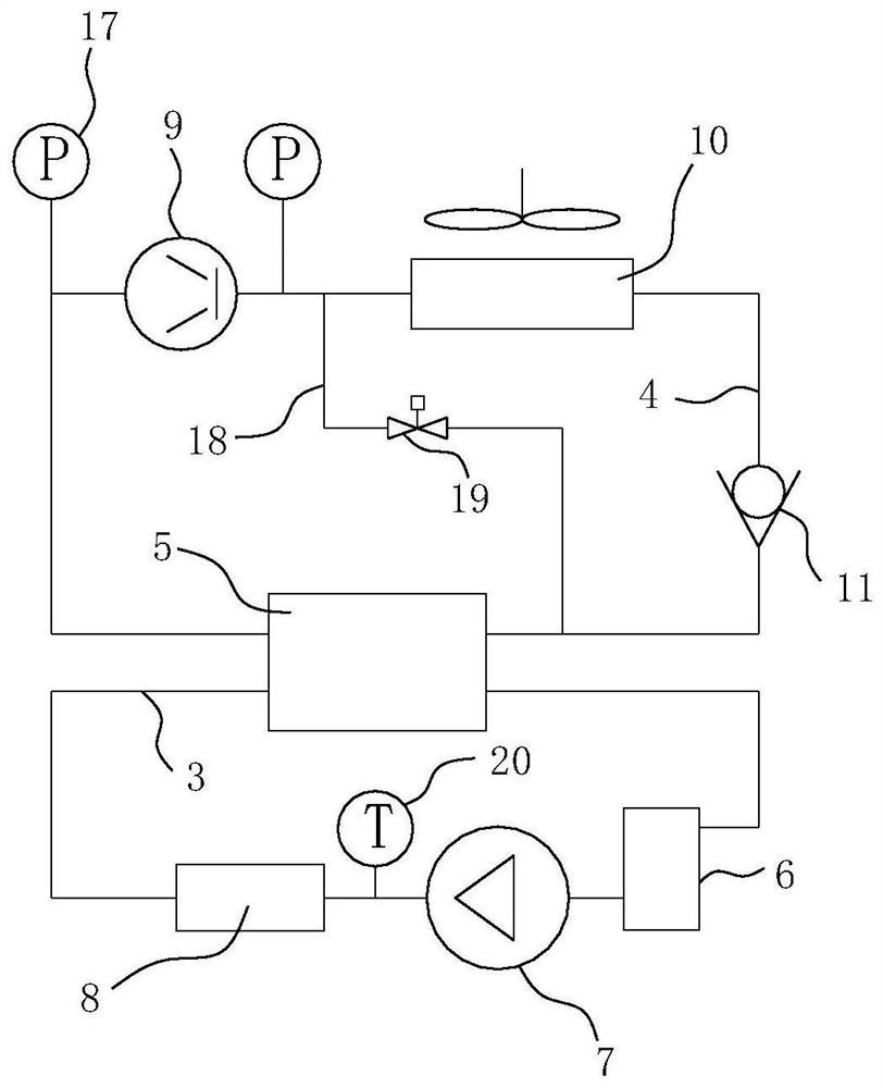
[0025] combine Figure 1-2 A phase-change heat extraction system shown includes a phase-change heat extraction circuit 3 for circulating phase-change medium and an active refrigeration circuit 4 for refrigerant circulation, and the phase-change heat extraction circuit 3 and active refrigeration circuit 4 meet In the same heat exchanger 5, and the phase change medium and the refrigerant perform heat exchange in the heat exchanger 5. In other words, there are two paths on the heat exchanger, one of which is connected to the phase change heat extraction circuit 3, and the other path is connected to the active refrigeration circuit 4, and the refrigerant in the active refrigeration circuit 4 is in the heat exchanger 5. The evaporated phase-change medium is refrigerated to recondense to a liquid state. The heat exchanger 5 can be a plate heat exchanger, a casing heat exchanger or the like.

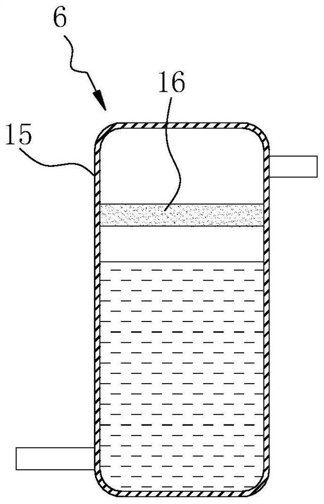
[0026] The phase change heat extraction circuit 3 is provided with a liquid storage tank ...


PUM


Abstract

The invention relates to the technical field of refrigeration, and aims at providing a novel phase change heat getting system good in cooling effect. According to the technical scheme, the novel phasechange heat getting system comprises a phase change heat getting loop allowing a phase change medium to circularly flow and an active refrigeration loop allowing a refrigerant to circularly flow. Thephase change heat getting loop and the active refrigeration loop are intersected into the same heat exchanger, the phase change medium and the refrigerant are subjected to heat exchange in the heat exchanger, and the system has good cooling effect and other electricity devices with high heat power.

Description

technical field [0001] The invention relates to the technical field of refrigeration, in particular to a phase change heat extraction system. Background technique [0002] At present, most of the heat dissipation of LED lighting systems on the market is to reduce the temperature of the chip through natural convection. For natural convection heat dissipation, there are currently two main methods: one is that the LED chip is directly bonded to the heat dissipation fins. , the heat is conducted to the fins through the solid heat, and then the heat is released to the environment through the heat exchange between the fin surface and the air. Second, for occasions where the LED power is large, the limited heat exchange area can no longer completely take away the heat of the chip, which will cause the LED chip to overheat, and the life of the chip will be greatly reduced or damaged. thermal area. Although the above two heat dissipation methods do not consume additional cooling po...

Claims


Application Information

Patent Timeline
Patent Type & Authority Patents(China)
IPC IPC(8): F21V29/52F25B1/00
CPCF25B1/00F21V29/52
Inventor 李宗伟郑平
Owner MIANYANG TIANHE MACHINERY MFG
Why Eureka
Try Eureka