Injection molding part appearance detection method and system based on stroboscopic light source

A technology for appearance inspection and injection molding, applied in the field of visual inspection, can solve the problem of high cost, achieve the effect of accurate lighting, simplify the lighting scheme, and improve the detection efficiency

Inactive Publication Date: 2019-08-23
HUAZHONG UNIV OF SCI & TECH
View PDF7 Cites 5 Cited by
  • Summary
  • Abstract
  • Description
  • Claims
  • Application Information

AI Technical Summary

Problems solved by technology

However, for some products, the size of the appearance defect only accounts for about 1% of the appearance size of the part. Compared with the size of the whole part, the size of the defect is negligible, and the position of the defect is random, so it is necessary to detect the appearance of the entire product In order to judge the specific location of the defect, it is necessary to set up multiple light sources to illuminate the entire product for a long time, which is costly

Method used


Image

  • Injection molding part appearance detection method and system based on stroboscopic light source
  • Injection molding part appearance detection method and system based on stroboscopic light source
  • Injection molding part appearance detection method and system based on stroboscopic light source

Examples


Embodiment Construction

[0026] In order to make the object, technical solution and advantages of the present invention clearer, the present invention will be further described in detail below in conjunction with the accompanying drawings and embodiments. It should be understood that the specific embodiments described here are only used to explain the present invention, not to limit the present invention. In addition, the technical features involved in the various embodiments of the present invention described below can be combined with each other as long as they do not constitute a conflict with each other.

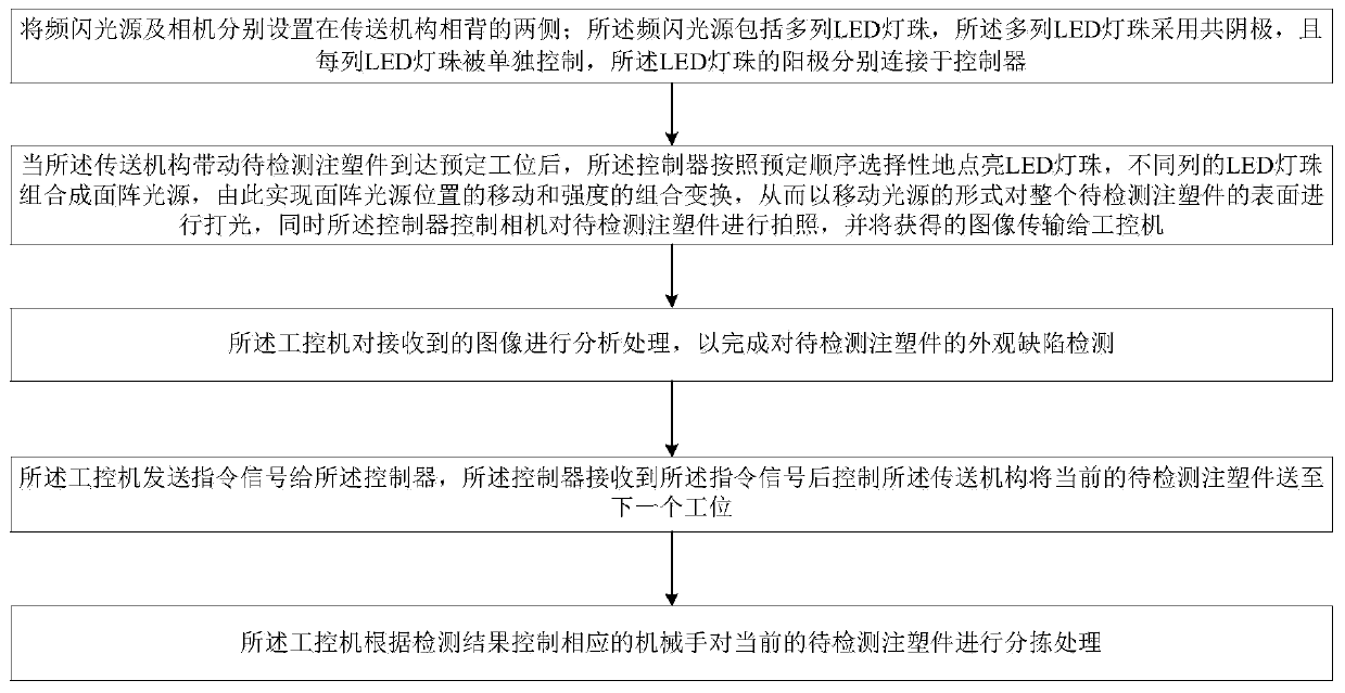
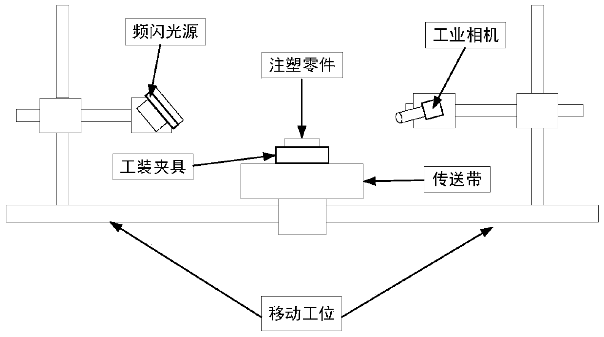
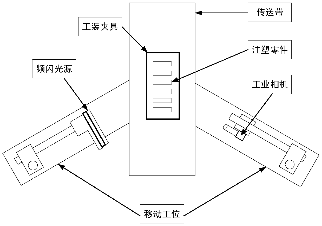
[0027] see figure 1 , figure 2 and image 3 , the method for inspecting the appearance of injection molded parts based on stroboscopic light source provided by the present invention, the method for inspecting the appearance of injection molded parts is suitable for the detection of appearance defects of elongated injection molded parts, and mainly includes the following steps:

[0028] Step ...


PUM


Abstract

The invention belongs to the related technical field of visual detection and discloses an injection molding part appearance detection method and system based on a stroboscopic light source; the methodcomprises the following steps that (1) the stroboscopic light source and a camera are arranged on the two opposite sides of a transmission mechanism respectively; the stroboscopic light source comprises multiple rows of LED lamp beads with common cathodes, and anodes of the LED lamp beads are connected with a controller separately; and (2) when the to-be-detected injection molding part reaches apreset station, the controller selectively turns on the corresponding LED lamp beads, and the different columns of lamp beads are combined into a surface array light source, so that the combination conversion of the movement and intensity of the surface array light source positions is realized, the whole to-be-tested injection molding part is polished in the form of a mobile light source; meanwhile, the controller controls the camera to carry out photographing on the to-be-detected injection molding part, and transmits the obtained image to an industrial personal computer; and (3) the industrial personal computer analyzes and processes the received image so as to detect the appearance defect of the injection molding part to be detected. According to the method, the cost is lowered, and theflexibility and applicability are improved.

Description

technical field [0001] The invention belongs to the technical field related to visual inspection, and more specifically relates to a method and system for inspecting the appearance of injection molded parts based on a stroboscopic light source. Background technique [0002] Plastic products are one of the most common materials in life. The proportion of plastic products in daily life is increasing, especially in the 3C field of digital products. With the increasing demand for plastic products, the demand for production automation of injection molded parts is increasing. It is becoming more and more urgent. In the current production environment, the process of feeding, forming, and taking parts in the injection molding production technology link has already been automated. However, due to the existence of subjective factors, it is difficult to automate the appearance quality monitoring of injection molding products, and still requires a lot of Manual inspection not only limit...

Claims


Application Information

Patent Timeline
Patent Type & Authority Applications(China)
IPC IPC(8): G01N21/88G01N21/95
CPCG01N21/8806G01N21/95
Inventor 张云刘家欢胡诗尧黄志高周华民
Owner HUAZHONG UNIV OF SCI & TECH
Why Eureka
Try Eureka