Laser radar system and laser scanning control method

A laser radar and laser beam technology, applied in the radio wave measurement system, electromagnetic wave re-radiation, utilization of re-radiation, etc., can solve problems such as insufficient scanning angle, limited deflection angle of MEMS galvanometer, insufficient scanning field of view, etc.

Active Publication Date: 2019-08-23
SUTENG INNOVATION TECH CO LTD
View PDF15 Cites 12 Cited by
  • Summary
  • Abstract
  • Description
  • Claims
  • Application Information

AI Technical Summary

Problems solved by technology

However, one of the main problems of MEMS lidar is that the deflection angle of the MEMS galvanometer is limited, resulting in insufficient scanning angle, which limits the scanning field of view.
Usually, the mechanical scanning angle of a single MEMS galvanometer is generally ±5°, that is, the scanning field of view is ±10°, which is far from enough for the scanning field of view in scenarios such as automatic driving or assisted driving.
[0004] In short, the current lidar system has the problem that the scanning field of view is too small

Method used


Image

  • Laser radar system and laser scanning control method
  • Laser radar system and laser scanning control method
  • Laser radar system and laser scanning control method

Examples


Embodiment Construction

[0031] In order to make the purpose, technical solution and advantages of the present application clearer, the present application will be further described in detail below in conjunction with the accompanying drawings and embodiments. It should be understood that the specific embodiments described here are only used to explain the present application, and are not intended to limit the present application.

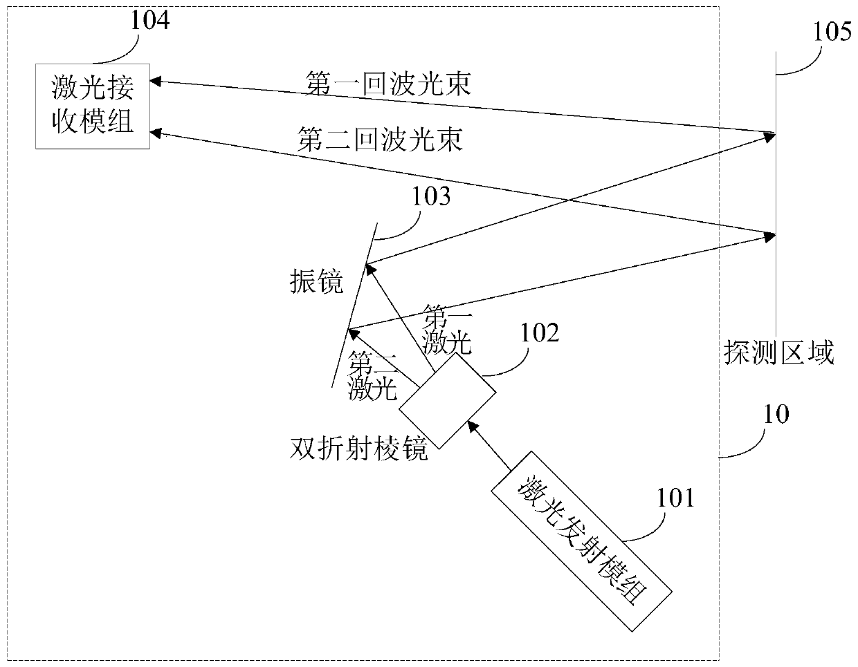
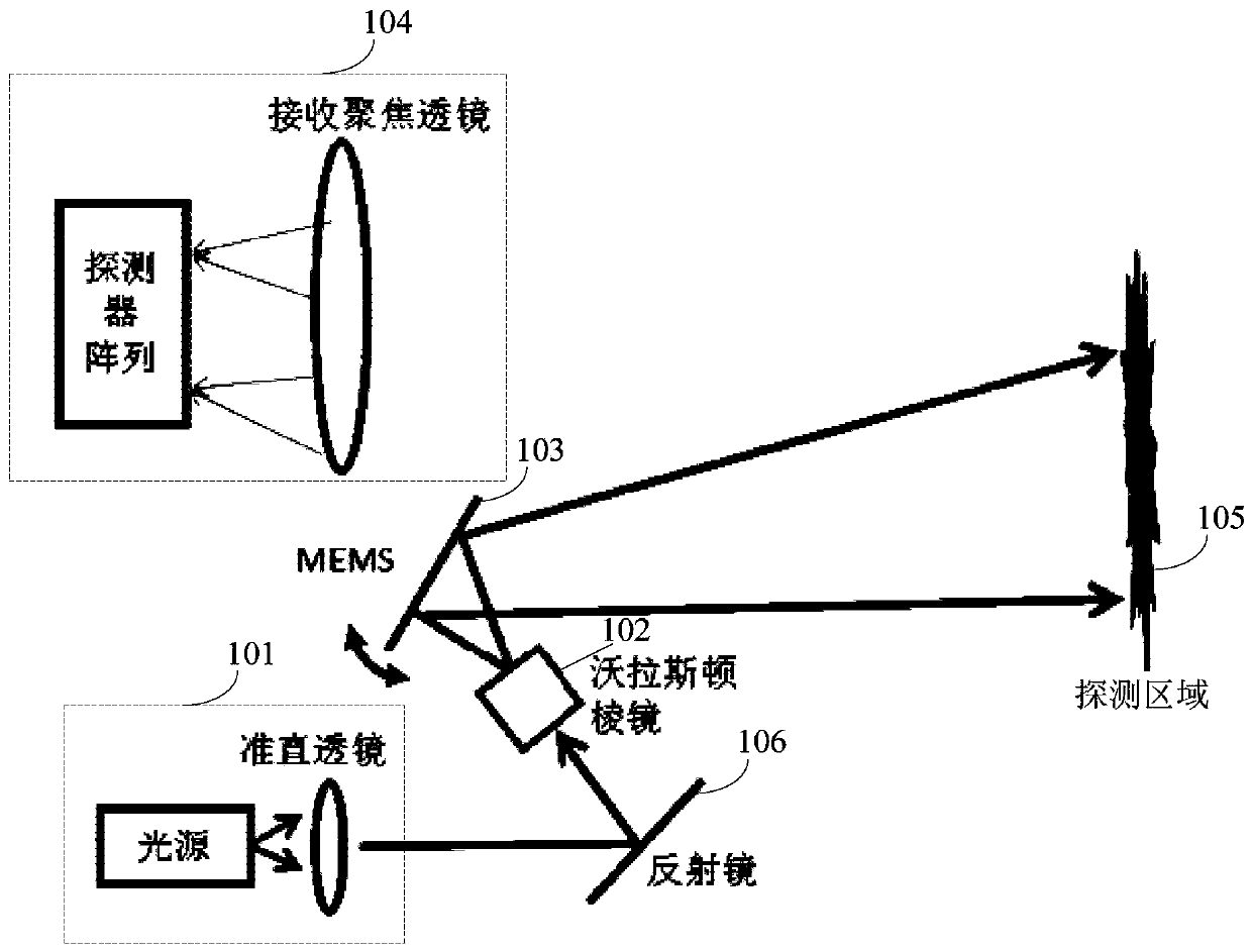
[0032] refer to figure 1 , shows a schematic structural diagram of a lidar system in this embodiment. Wherein, the laser radar system 10 may include: a laser emitting module 101, a birefringent prism 102, a vibrating mirror 103 and a laser receiving module 104;

[0033] Laser emitting module 101, used to emit laser beams;

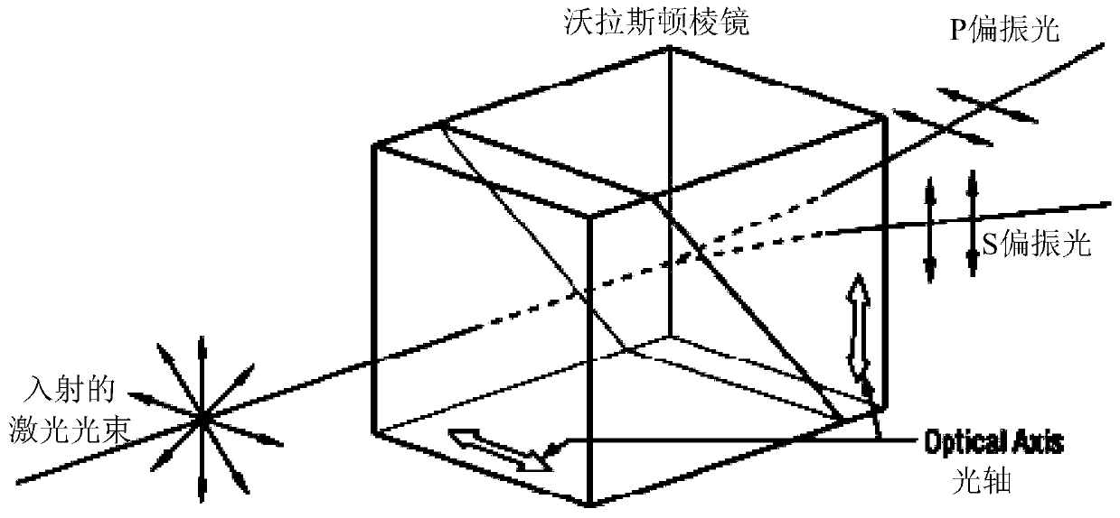
[0034] The birefringent prism 102 is used to split the laser beam into a first laser beam and a second laser beam that go out to the vibrating mirror 103; there is an angle between the first laser beam and the second laser beam;

[0035] A vibrating ...


PUM


Abstract

The invention relates to a laser radar system and a laser scanning control method. The laser radar system can comprise a laser emission module, a double-refracting prism, a galvanometer and a laser reception module, wherein the laser emission module is used for emitting a laser beam; the double-refracting prism is used for separating the laser beam into first laser and second laser emitted towardthe galvanometer; an included angle exists between the first laser and the second laser; the galvanometer is used for reflecting the first laser and the second laser to different positions of a detection area; the laser reception module is used for respectively receiving a first echo light beam and a second echo light beam reflected back from the detection area; the first echo light beam is laser,reflected back by an object in the detection area, of the first laser; and the second echo light beam is laser, reflected back by the object in the detection area, of the second laser. By adoption ofthe laser radar system, the scanning field angle can be improved.

Description

technical field [0001] The present application relates to the technical field of laser radar, in particular to a laser radar system and a laser scanning control method. Background technique [0002] At present, one of the main problems of lidar technology is how to realize the scanning of light beams, which is also the key to the advancement of lidar technology in laser ranging technology. [0003] Among them, Micro-Electro-Mechanical System (MEMS, Micro-Electro-Mechanical System) lidar generally uses the vibration of the MEMS vibrating mirror to realize beam scanning. However, one of the main problems of MEMS lidar is that the deflection angle of the MEMS galvanometer is limited, resulting in insufficient scanning angle, which limits the scanning field of view. Usually, the mechanical scanning angle of a single MEMS galvanometer is generally ±5°, that is, the scanning field of view is ±10°, which is far from enough for the scanning field of view in scenarios such as automa...

Claims


Application Information

Patent Timeline
Patent Type & Authority Applications(China)
IPC IPC(8): G01S17/08G01S7/487G01S7/493G01S7/481G01S7/495
CPCG01S17/08G01S7/487G01S7/493G01S7/481G01S7/495
Inventor 罗斯特刘夏王吉魏威郑景扬刘冬山
Owner SUTENG INNOVATION TECH CO LTD
Why Eureka
Try Eureka