
Integrated DC power flow controller with fault current limiting and circuit breaking functions

A DC power flow and fault current limiting technology, applied in the field of power transmission and distribution, can solve the problem of lack of fault current limiting capability, and achieve the effect of reducing application and cost

Inactive Publication Date: 2019-08-23
NORTH CHINA ELECTRIC POWER UNIV (BAODING)
View PDF4 Cites 3 Cited by
  • Summary
  • Abstract
  • Description
  • Claims
  • Application Information

AI Technical Summary

Problems solved by technology

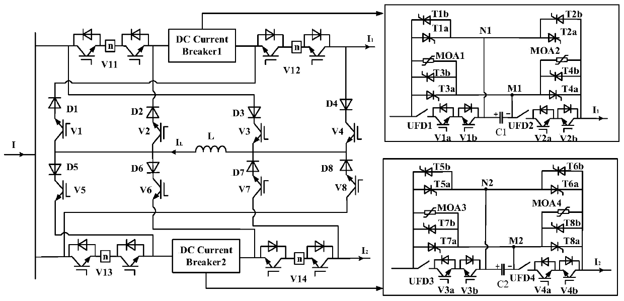
The literature "Research on Simulation Modeling of DC Circuit Breaker with Power Flow Control Function" proposes a DC circuit breaker structure that can realize power flow control, but does not have fault current limiting capability

Method used


Image

  • Integrated DC power flow controller with fault current limiting and circuit breaking functions
  • Integrated DC power flow controller with fault current limiting and circuit breaking functions
  • Integrated DC power flow controller with fault current limiting and circuit breaking functions

Examples


Embodiment Construction

[0019] In order to further illustrate the performance and working principle of the present invention, the composition and working principle of the invention will be described in detail below in conjunction with the accompanying drawings.

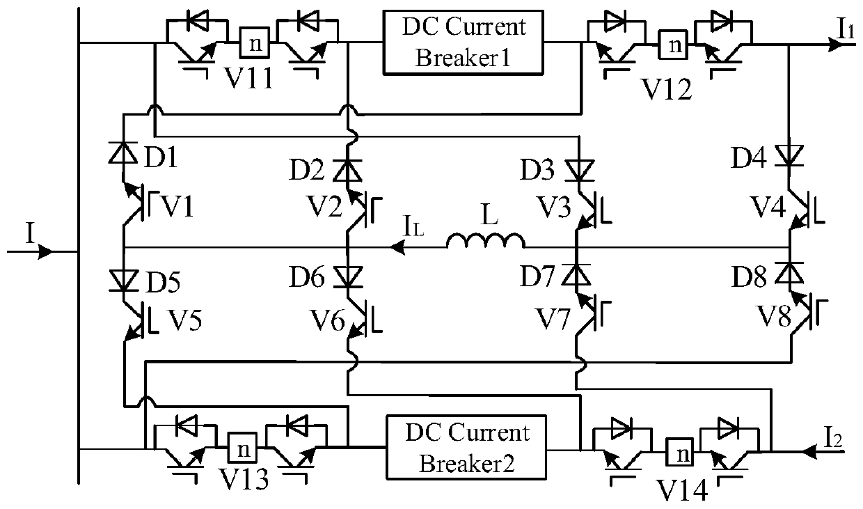
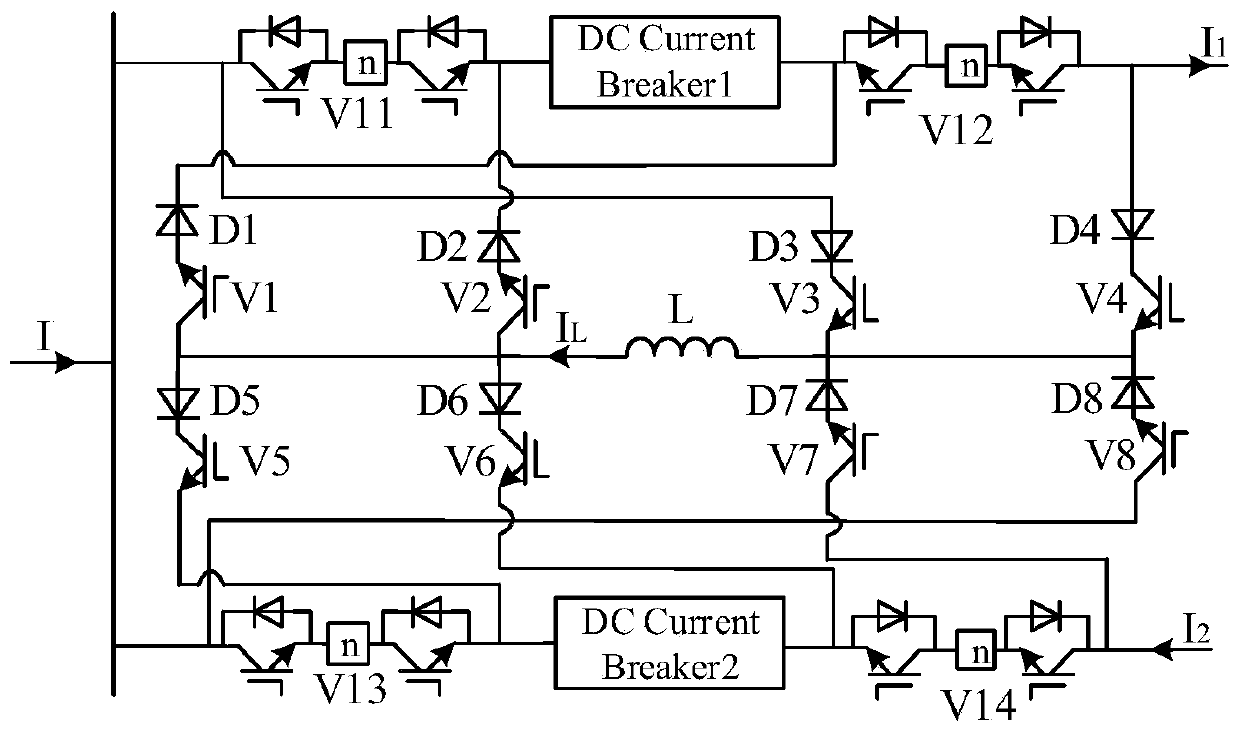
[0020] The present invention is applicable to two line current I 1 , I 2 It is the working condition when a single-pole ground fault occurs in different directions and any one of the two lines. Such as figure 2 Shown, with current I, I 1 The direction is from left to right, the current I 2 The direction is from right to left as an example to illustrate the working mode of the invention.

[0021] Under normal working conditions, the fault current suppression and fault line removal functions are blocked, and the power flow control function is put into use. The current of the DC circuit breaker on the line is as follows: Figure 7 shown. The power flow control requirement is to regulate the current I 1 increase. Depend on figure 2 I...


PUM


Abstract

The invention provides an integrated DC power flow controller topology with fault current limiting and circuit breaking functions. The topology includes a power flow controller portion with the current limiting capability and a DC circuit breaker portion on two lines, the two share a capacitive branch, wherein the power flow controller portion controls on / off of a switch tube under normal operating conditions to make shared inductor time sharing in parallel with capacitors on both lines, the three exchange energy to control the line power flow, when a ground fault occurs on a certain line, thepower flow control capability is blocked, a shared inductor is connected in series with the faulty line for current limiting, moreover, a DC circuit breaker on the faulty line is started, on / off of athyristor is controlled by the voltage of the capacitor on the line at the power flow control phase, and the capacitors are connected in parallel with a lightning arrester to charge the capacitors. The topology is advantaged in that conduction of the lightning arrester is finally triggered, fault current consumption is in the lightning arrester branch, and disconnection of the faulty line is achieved.

Description

technical field [0001] The invention belongs to the technical field of power transmission and distribution, and in particular relates to a composite direct current flow controller topology with fault current limiting and circuit breaking capabilities. Background technique [0002] Multi-terminal DC transmission and DC grid technology, as an effective means to solve the problem of large-scale renewable energy grid integration and consumption, has become one of the important directions of future power system research and development. The DC power grid is characterized by meshes and redundancy, and there may be multiple transmission lines between converter stations, which improves the flexibility and reliability of the system, and at the same time makes the problems of power flow control and fault protection more prominent. When the number of branches in the system is greater than the number of converter stations, there will be a problem of insufficient degrees of freedom. At t...

Claims


Application Information

Patent Timeline
Patent Type & Authority Applications(China)
IPC IPC(8): H02J3/06H02H7/26
CPCH02H7/262H02J3/06
Inventor 许建中李馨雨宋冰倩赵成勇
Owner NORTH CHINA ELECTRIC POWER UNIV (BAODING)
Learn More