Eureka AIR delivers breakthrough ideas for toughest innovation challenges, trusted by R&D personnel around the world.

Self-adaptive bipolar amplifier with linear bias circuit

A bias circuit, bipolar technology, used in amplifiers with semiconductor devices/discharge tubes, amplifiers, high-frequency amplifiers, etc., can solve problems such as no solutions, and achieve the effect of improving linearity and efficiency

Pending Publication Date: 2019-08-23
澋芯微电子(重庆)有限公司
View PDF4 Cites 1 Cited by
  • Summary
  • Abstract
  • Description
  • Claims
  • Application Information

AI Technical Summary

Problems solved by technology

[0004] For the problems in related technologies, no effective solutions have been proposed yet

Method used


Image

  • Self-adaptive bipolar amplifier with linear bias circuit
  • Self-adaptive bipolar amplifier with linear bias circuit

Examples


Embodiment Construction

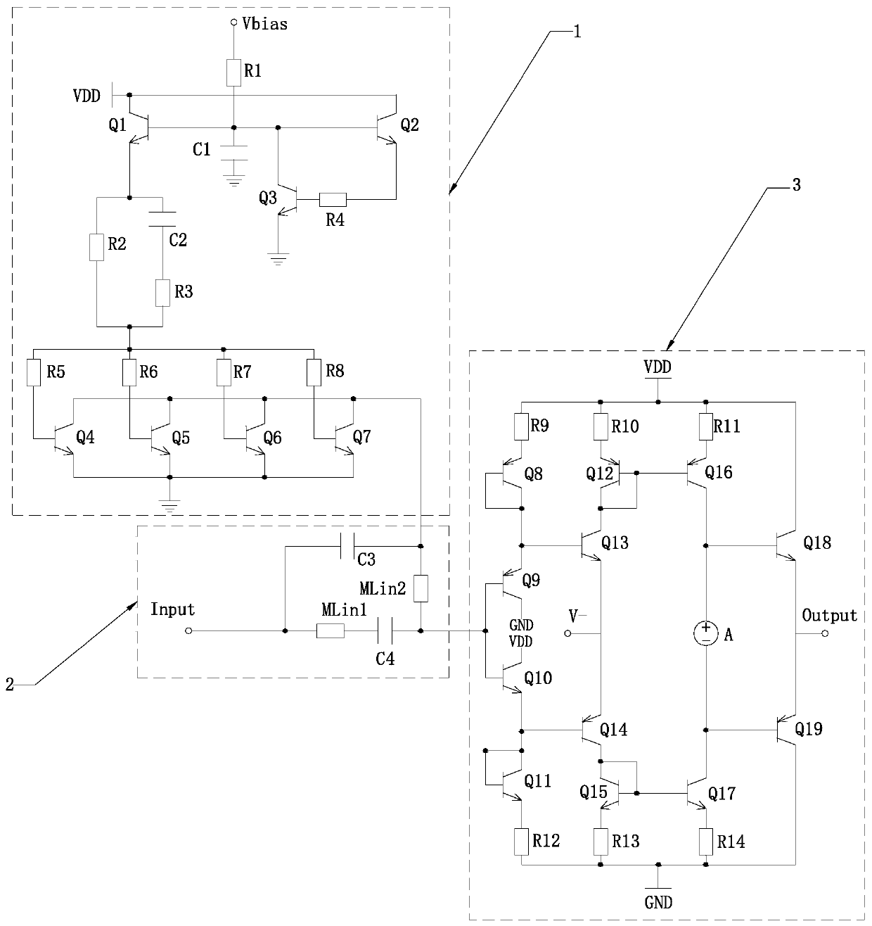
[0026] In order to further illustrate the various embodiments, the present invention provides accompanying drawings, which are part of the disclosure of the present invention, and are mainly used to illustrate the embodiments, and can be used in conjunction with the relevant descriptions in the specification to explain the operating principles of the embodiments, for reference Those of ordinary skill in the art should be able to understand other possible implementations and advantages of the present invention. The components in the figures are not drawn to scale, and similar component symbols are generally used to represent similar components.

[0027] According to an embodiment of the present invention, an adaptive bipolar amplifier with a linear bias circuit is provided.

[0028] Now in conjunction with accompanying drawing and specific embodiment the present invention is further described, as figure 1 As shown, an adaptive bipolar amplifier with a linear bias circuit accor...


PUM


Abstract

The invention discloses a self-adaptive bipolar amplifier with a linear bias circuit, which comprises a linear bias circuit, a self-adaptive circuit and a bipolar amplifier. The self-adaptive bipolaramplifier is connected with the bipolar amplifier through the self-adaptive circuit. The bipolar amplifier has the beneficial effects that the bias current of the radio frequency power amplifier tubecan be changed by changing the size of the constant current source IDC, so that the radio frequency power amplifier tube can select the bias state according to the output power, the linear requirement can be met, and the influence on the power efficiency is small. A coupling capacitor C4 and two sections of microstrip lines are added on the basis of a traditional linearization biasing circuit, and the self-adaptive linearization biasing circuit enables a power amplifier unit to be in a relatively stable conduction angle state along with increase of input power, so that an optimal state of linearity and efficiency is achieved.

Description

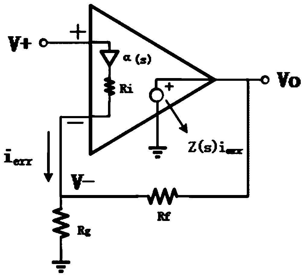
technical field [0001] The invention relates to the technical field of amplifiers, in particular to an adaptive bipolar amplifier with a linear bias circuit. Background technique [0002] The bipolar amplifier is usually a current feedback type, and its DC characteristics are not good. It is suitable for amplifying high-frequency AC signals. The resistance is a constant value. figure 2 It is the schematic diagram of the current feedback operational amplifier. First, the input terminal of the current feedback operational amplifier is not the differential input terminal of the voltage feedback amplifier circuit, but a follower circuit with a gain close to 1 from V+ to V- input terminal. This Following the input stage, there is an output resistance Ri close to 0, and the error current signal used for feedback flows through Ri and flows in or out from the V- port. The error current is mirrored to the gain impedance Z(s) of the second stage to form a voltage. The second stage ...

Claims


Application Information

Patent Timeline
Patent Type & Authority Applications(China)
IPC IPC(8): H03F1/32H03F3/189H03F3/24
CPCH03F1/32H03F3/189H03F3/245
Inventor 李程坡黄天聪
Owner 澋芯微电子(重庆)有限公司
Why Eureka
Eureka Blog
Learn More