
A kind of wire cutting equipment suitable for processing the stress groove of connecting rod expansion

A technology of stress groove and wire cutting, which is applied in the direction of electric processing equipment, metal processing equipment, manufacturing tools, etc., can solve the problems of low processing efficiency, increased cost, inconvenient operation, etc., achieve accurate processing accuracy, save cutting lines, and operate convenient effect

Active Publication Date: 2021-03-19
NANGONG JINGQIANG CONNECTING ROD CO LTD
View PDF12 Cites 1 Cited by
  • Summary
  • Abstract
  • Description
  • Claims
  • Application Information

AI Technical Summary

Problems solved by technology

This method has the following disadvantages: inconvenient operation, low processing efficiency, and repeated manual threading and winding, which is easy to cut fingers and has great potential safety hazards
Repeated threading will cause the wire cutting line to be easily broken, resulting in an increase in cost
[0005] For the problems in related technologies, no effective solutions have been proposed yet

Method used


Image

  • A kind of wire cutting equipment suitable for processing the stress groove of connecting rod expansion
  • A kind of wire cutting equipment suitable for processing the stress groove of connecting rod expansion
  • A kind of wire cutting equipment suitable for processing the stress groove of connecting rod expansion

Examples


Embodiment Construction

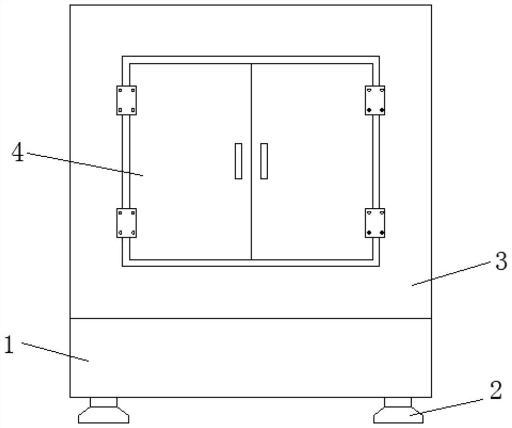
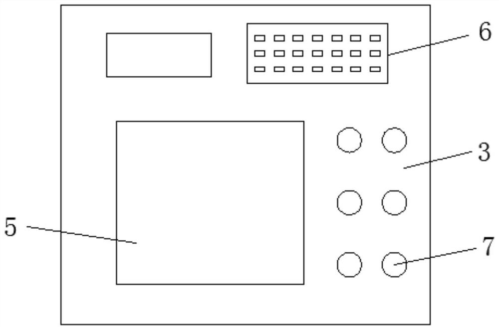
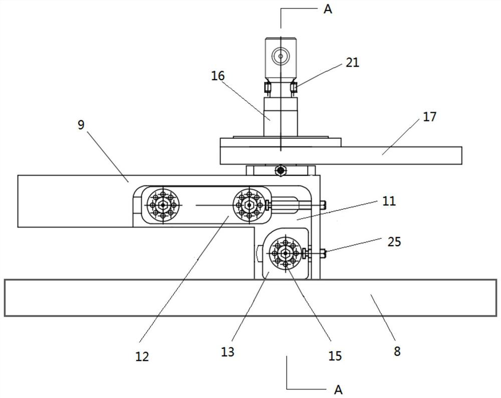
[0029] In order to further illustrate the various embodiments, the present invention provides accompanying drawings, which are part of the disclosure of the present invention, and are mainly used to illustrate the embodiments, and can be used in conjunction with the relevant descriptions in the specification to explain the operating principles of the embodiments, for reference Those of ordinary skill in the art should be able to understand other possible implementations and advantages of the present invention. The components in the figures are not drawn to scale, and similar component symbols are generally used to represent similar components.

[0030] According to an embodiment of the present invention, a wire-cutting device suitable for processing the expansion stress groove of a connecting rod is provided.

[0031] Now in conjunction with accompanying drawing and specific embodiment the present invention is further described, as Figure 1-5 As shown, according to an embodim...


PUM


Abstract

The invention discloses wire cutting equipment suitable for machining a connecting rod expansion stress groove. The wire cutting equipment comprises a control cabinet, a shell is arranged at the top of the control cabinet, a bottom plate is arranged at the inner bottom of the shell, a vertical plate is arranged at the top of the bottom plate, a mounting groove is formed in the bottom of the vertical plate in a penetrating mode, a first guide wheel seat is arranged at the inner top of the mounting groove, a second guide wheel seat is arranged at the inner bottom of the mounting groove, a secondguide wheel assembly is arranged inside the second guide wheel seat, a wire vertical rod is arranged on one side of the top of the vertical plate, and a connecting rod fixing mechanism matched with the vertical plate is arranged on the top of the vertical plate and located on the outer side of the bottom of the wire vertical rod in a sleeved mode. The equipment has the beneficial effects that through using of the equipment, the groove cutting depth can be freely adjusted according to the expansion effect through the equipment, the quality of the expansion section can be used for adjusting parameters, so that the corresponding effect is achieved, the stress groove is convenient and fast to machine, the machining precision is accurate and safe, and the cost is saved.

Description

technical field [0001] The invention relates to the field of cutting equipment, in particular to a wire cutting equipment suitable for processing the expansion stress groove of a connecting rod. Background technique [0002] Expansion connecting rod is a newly emerging connecting rod processing technology in recent years. Its principle is to use a non-quenched and tempered steel as the material of the connecting rod, which not only ensures the relevant performance of the connecting rod, but also requires a certain degree of brittleness. The big head hole is designed in the form of expansion. [0003] Expansion of the connecting rod is to process a stress groove in the big head hole of the connecting rod, and use a special expansion device to break a whole big head hole into two semicircular holes, and the expansion section forms an uneven surface, and then the connecting rod bolts The uneven surfaces are reassembled together. This process not only reduces the increased proc...

Claims


Application Information

Patent Timeline
Patent Type & Authority Patents(China)
IPC IPC(8): B23H7/10
CPCB23H7/102B23H7/104B23H7/105
Inventor 史延辰王金凯毕风豪齐少辉任恒胜吴勇
Owner NANGONG JINGQIANG CONNECTING ROD CO LTD
Learn More