Curvature regulating member and power supply device

A technology of bending control and components, which is applied in the field of power supply devices and bending control components, and can solve problems such as damage to connecting hinges

Active Publication Date: 2019-08-27
YAZAKI CORP
View PDF7 Cites 3 Cited by
  • Summary
  • Abstract
  • Description
  • Claims
  • Application Information

AI Technical Summary

Problems solved by technology

In the case where a load is applied in the width direction, adjacent bent portions 11 may be displaced relative to each other in the width direction, and this may result in damage to the connecting hinge 12

Method used


Image

  • Curvature regulating member and power supply device
  • Curvature regulating member and power supply device
  • Curvature regulating member and power supply device

Examples


Embodiment Construction

[0035] Hereinafter, a bending control member and a power supply device according to an embodiment of the present invention will be described with reference to the accompanying drawings.

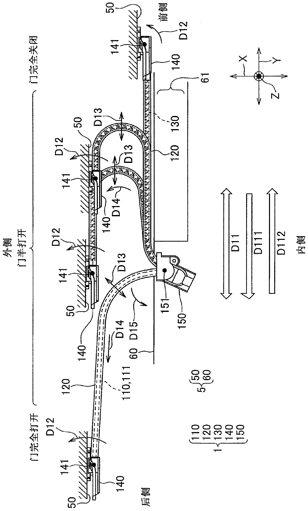
[0036] figure 1 is a view showing a power supply device to which a bending control member according to an embodiment of the present invention is applied. The power supply device 1 of the present embodiment is configured to be mounted to a vehicle 5 . The power supply device 1 is configured to supply electric power from a power source (not shown) arranged on the vehicle body 60 side to an electronic device (not shown) arranged on the sliding door 50 (sliding member) via a wire harness 110 . exist figure 1 Among them, the right side corresponds to the front side of the vehicle 5 , the left side corresponds to the rear side of the vehicle 5 , the upper side corresponds to the outer side of the vehicle 5 , and the lower side corresponds to the inner side of the vehicle 5 . That is, in the dr...


PUM


Abstract

A curvature regulating member includes a plurality of member pieces to be arranged along a wire harness and a flexible connecting part connecting adjacent member pieces. The adjacent member pieces areconfigured to contact each other, thereby regulating curvature of the wire harness on an X-Y plane. Each member piece includes a recessed part recessed toward a direction away from an adjacent memberpiece on one side, and a second protrusion configured to be inserted in the recessed part provided on an adjacent member piece on another side when adjacent member pieces contact each other. The recessed part includes a slanted face extending away from the adjacent member piece on the one side as leaving from both ends in a widthwise direction. The second protrusion includes a slanted face extending toward the adjacent member piece on the another side as leaving from both ends in the widthwise direction.

Description

technical field [0001] The present invention relates to a bend control member for controlling the bend of a wire harness and a power supply device to which the bend control member is applied. Background technique [0002] One example of a conventional bending control member as described above is shown as an example in Patent Document 1 mentioned below. Figure 9 The bending control member 10 shown in patent document 1 is shown. As shown, the bending control member 10 is arranged along the wire harness 20 and is configured to control the wire harness 20 so that the wire harness 20 cannot be bent at a curvature radius equal to or smaller than a reference radius. The bending control member 10 includes a plurality of bent portions 11 bent at a reference radius, and connecting hinges 12 (connecting portions) connecting the bent portions 11 . The plurality of bent portions 11 are arranged along the wire harness 20 and are formed with a substantially U-shaped cross section. The c...

Claims


Application Information

Patent Timeline
Patent Type & Authority Applications(China)
IPC IPC(8): B60R16/027H02G11/00
CPCB60R16/027H02G11/00B60R16/0215H02G3/0462
Inventor 加藤光伸关野司大塚龙也横山真树
Owner YAZAKI CORP
Why Eureka
Try Eureka