Yaw brake disc of wind turbine generator system
A technology for wind turbines and brake discs, which is applied in the control of wind turbines, wind turbines, and wind power generation, etc., can solve the problems of large friction lining loss, inconvenient maintenance, installation or replacement, and high installation costs, so as to increase service life and achieve economical benefits. The effect of maintenance and safety improvement
- Summary
- Abstract
- Description
- Claims
- Application Information
AI Technical Summary
Problems solved by technology
Method used
Image

Examples
Embodiment 1
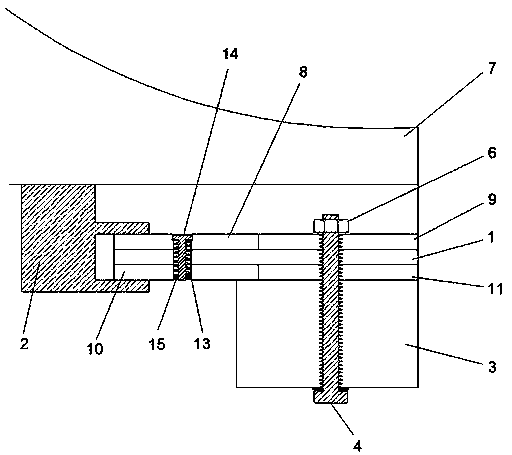
[0023] Embodiment one, such as Figure 1 to Figure 2 As shown, a yaw brake disc of a wind power generating set includes a brake disc base 1 and a brake brake 2, the upper surface of the brake disc base 1 is fixedly connected with an upper brake disc, and the lower surface of the brake disc base 1 is fixedly connected with a lower end brake disc, A tower flange 3 is arranged below the brake disc at the lower end, and one end of the bolt 4 is movably connected to the bottom of the tower flange 3 through threads, and the other end of the bolt 4 passes through the tower flange 3, the brake disc at the lower end, the brake disc base 1 and the The upper brake disc is threadedly connected with a nut 6; the brake brake 2 is fixedly installed on the lower surface of the bed plate 7 of the generator set, and the clamping ends of the brake brake 2 are in contact with the upper brake disc and the lower brake disc respectively.
[0024] Therefore, when the upper brake disc or the lower bra...
Embodiment 2
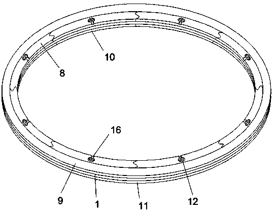
[0025] Embodiment 2, based on the further improvement of Embodiment 1, the upper brake disc includes an upper inner inner ring brake disc 8 and an upper outer outer ring brake disc 9, the upper inner inner ring brake disc 8 and the upper outer outer ring brake disc 9 are arranged concentrically, and the lower end brake disc includes The lower end inner ring brake disc 10 and the lower end outer ring brake disc 11 are arranged concentrically; the fixing bolts 4 pass through the tower flange 3, the lower end outer ring brake disc 11, The brake disc base 1 and the upper end outer ring brake disc 9 are threadedly connected with the nut 6, and the clamping ends of the brake brake 2 are in contact with the upper end inner ring brake disc 8 and the lower end inner ring brake disc 10 respectively. The upper inner ring brake disc 8 and the lower inner ring brake disc 10 are respectively provided with a first groove 12 and a second groove 13, and the first groove 12 is provided with a th...
Embodiment 3
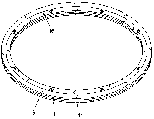
[0027] Embodiment 3, based on the further improvement of Embodiment 2, there are multiple upper inner ring brake discs 8 and lower inner ring brake discs 10, which are evenly distributed on the upper surface and lower surface of the brake disc base 1 respectively. By adopting the segmented design of the upper inner ring brake disc 8 and the lower inner ring brake disc 10, when wear occurs, the corresponding worn parts can be replaced individually, thereby greatly saving the replacement cost; and segmented The design is also convenient for the moving, tower installation and disassembly of components, which saves the hoisting cost of components, reduces the requirements for installation space, and facilitates operation and realization.
PUM
 Abstract
Description
Claims
Application Information
 - R&D
- Intellectual Property
- Life Sciences
- Materials
- Tech Scout
- Unparalleled Data Quality
- Higher Quality Content
- 60% Fewer Hallucinations
Browse by: Latest US Patents, China's latest patents, Technical Efficacy Thesaurus, Application Domain, Technology Topic, Popular Technical Reports.
© 2025 PatSnap. All rights reserved.Legal|Privacy policy|Modern Slavery Act Transparency Statement|Sitemap|About US| Contact US: help@patsnap.com