cable connector assembly

A cable connector and connector technology, which is applied in the direction of cable terminals, electrical components, and cable entry sealing devices, can solve the problems of seal failure, seal bending, and excessive wear of seals, and reduce the risk of excessive wear or damage Risk, the effect of reducing the number of parts

Active Publication Date: 2020-12-22
CMP PRODS
View PDF7 Cites 0 Cited by
  • Summary
  • Abstract
  • Description
  • Claims
  • Application Information

AI Technical Summary

Problems solved by technology

[0003] This known combination has the disadvantage that inserting the cable through the seal to position it to the gland body can cause excessive wear or momentary damage to the seal (especially if the cable end has been cut exposing sharp edges); and Threaded engagement between the first and second body to grip any cable armor or cable braid and / or secure any outer sealing ring to the cable can cause distortion of the seal which can which in turn causes further seal excessive wear or damage
A further disadvantage of this known combination is that, since the seal engages the cable when the cable is inserted through the gland body, pulling back the cable can cause a The seal is bent, which can cause the seal to fail

Method used


Image

  • cable connector assembly
  • cable connector assembly
  • cable connector assembly

Examples


Embodiment Construction

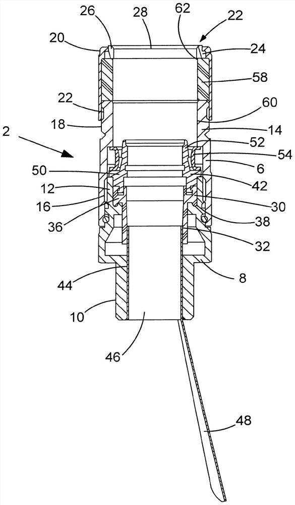
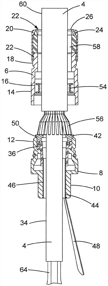
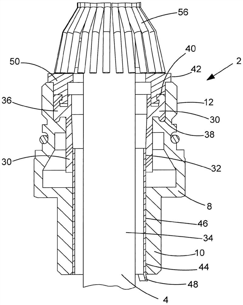
[0051] see figure 1 , used in the first embodiment of the present invention to install cables 4 ( figure 2 ) The cable connector assembly 2 in a housing (not shown) has a connector body 6 , and the connector body 6 includes a first body portion 8 and a second body portion 14 . The first body portion 8 has a first external thread 10 and a second external thread 12 for cooperating with the internal thread of a through hole in the housing (not shown) to install the cable 4 in the housing. The second body portion 14 has an internal thread 16 for cooperating with the second external thread 12 of the first body portion 8 , and an external thread 18 . The third body 20 has internal threads 22 for cooperating with the external threads 18 of the second body 14 and a through hole 22 for cooperating with the shoulder 24 of the ferrule 26 to locate the ferrule 26 . The ferrule 26 has a through hole 28 for the cable 4 to pass through.

[0052] The elastic first seal 30 has a first thro...


PUM


Abstract

A cable connector assembly (2) includes a connector body (6) for being installed on a cable, a first elastic sealing member (30) for forming a seal between the cable and the connector body and having a first through hole ), a seal opening device (44) for penetrating and enlarging the first through hole, the seal opening device (44) has a hollow body (46) so that part of the cable can The case passes through the first through hole, wherein the seal opening device can be removed from the connector body so that the first seal and the cable can be elastically combined.

Description

technical field [0001] The present invention relates to a cable connector assembly, in particular, but not limited to, a cable gland assembly for connecting a cable to enable the cable to be connected to a housing. Background technique [0002] Known cable glands for connecting cables to an enclosure hold cables passing through the cable gland in place and place a resilient seal on the exposed inner sheath of the cables passing through the seal's through-hole and the inner surface of the cable gland body. The partial seal acts as a diaphragm seal and by pushing the cable axially into the seal such that the partial seal grips the outer surface of the cable, the seal deforms to accommodate the cable, creating friction between the seal and the cable seal. Furthermore, a further portion of the seal may be compressed by a threaded fit between the first body and the second body, which forms a compression seal between the seal and the at least one first body. [0003] This known...

Claims


Application Information

Patent Timeline
Patent Type & Authority Patents(China)
IPC IPC(8): H02G3/06H02G15/013H02G3/08
CPCH02G15/013H02G3/0675H02G3/06H02G3/0666H02G15/04
Inventor 李·弗里泽尔
Owner CMP PRODS
Why Eureka
Try Eureka