Dust removal system for plastic particle production and processing

A plastic particle and dust removal system technology, which is applied in the direction of smoke removal, dispersed particle filtration, dispersed particle separation, etc., can solve the problem of low dust removal rate, and achieve the effect of reducing the requirements and volume of the factory building

Inactive Publication Date: 2019-08-30
CHONGQING JINGBANG HIGH MOLECULAR MATERIAL CO LTD
View PDF12 Cites 4 Cited by
  • Summary
  • Abstract
  • Description
  • Claims
  • Application Information

AI Technical Summary

Problems solved by technology

[0004] The main purpose of the present invention is to provide a dust removal system for the production and processing o

Method used


Image

  • Dust removal system for plastic particle production and processing
  • Dust removal system for plastic particle production and processing
  • Dust removal system for plastic particle production and processing

Examples


Embodiment 1

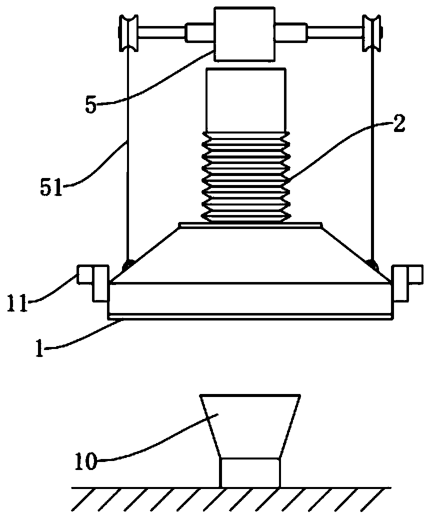
[0031] Dust removal system for the production and processing of plastic granules, such as figure 1 As shown, it includes a dust collection hood 1 and a bracket. The dust collection hood 1 is arranged at 2-2.5 m directly above the feed hopper 10, and is in the shape of an inverted funnel. Sliders 11 are welded on both sides of the dust collection cover 1, and a chute cooperating with the sliders 11 is fixed on the bracket. In order to make the dust collection hood 1 vertically lift and slide relative to the support, the double-axis motor 5 is fixed on the support, and the two output shafts of the double-axis motor 5 are connected with a winding wheel through a key, and a winding rope 51 is wound on the winding wheel. The lower end of the rope 51 is fixed with the outer wall of the dust collection cover 1 . When the motor rotates, the dust collection cover 1 can move up and down.

[0032] The dust collection hood 1 communicates with the telescopic air duct 2 through the flange...

Embodiment 2

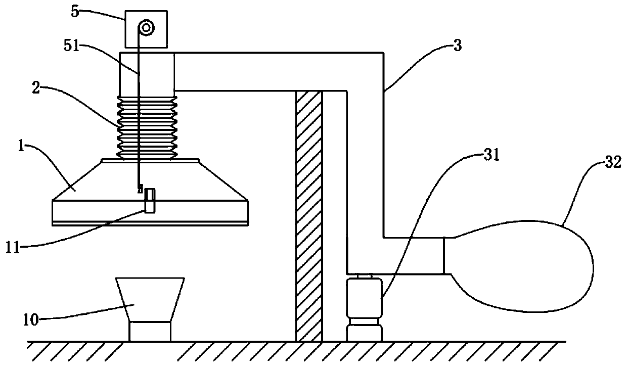
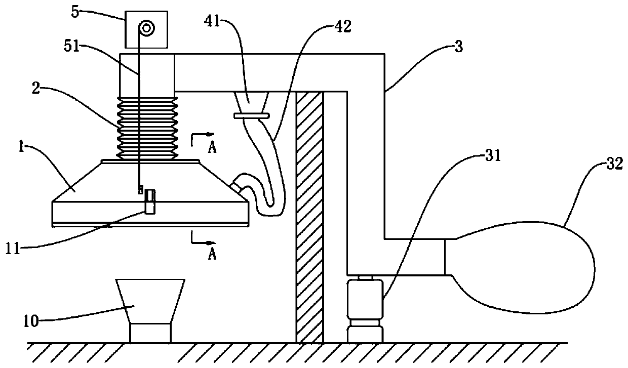
[0036] The difference from the embodiment is that, as Figure 4 As shown, near the suction pipe 43 is bonded to the lower edge of the dust collection hood 1, and the cross section of the near suction pipe 43 is J-shaped. The near suction pipe 43 is provided with a plurality of suction ports 44, and some suction ports 44 face the dust collection hood 1. Inside, some suction ports 44 are facing the outside of the dust collection hood 1 . Near suction pipe 43 is communicated with suction pipe 42, as image 3 As shown, the suction pipe 42 communicates with the auxiliary suction hood 41 , the auxiliary suction hood 41 is funnel-shaped, and the upper end of the auxiliary suction hood 41 communicates with the dust suction air duct 3 through a flange.

[0037] When negative pressure is generated in the dust suction duct 3, the dust suction port 44 can expand the suction area of ​​the dust suction hood 1 in the air during the descent of the dust suction hood 1. After the dust suction ...


PUM


Abstract

The invention relates to the technical field of plastic particle processing equipment, in particular to a dust removal system for plastic particle production and processing. The dust removal system comprises a support and a dust hood arranged above a feed hopper, wherein the dust hood is vertically and slidably connected with the support through a connecting piece, the dust hood communicates witha telescopic air pipe, the telescopic air pipe communicates with a dust suction air pipe, the dust suction air pipe is connected with a negative pressure dust suction device, after the dust hood slides vertically downwards, a gap is left between the dust hood and the floor, a motor is fixed on the support, an output shaft of the motor is fixedly connected with a winding wheel, the winding wheel iswound with a winding rope, and the lower end of the winding rope is fixed with the dust hood. According to the scheme of the system, the technical problem of low dust removal rate near the feed hopper in the prior art is solved by changing the distance between the dust hood and the feed hopper, and the cleanness of the working environment of workers is improved.

Description

technical field [0001] The invention relates to the technical field of plastic particle processing equipment, in particular to a dust removal system for plastic particle production and processing. Background technique [0002] In the plastic granule production line, it is necessary to add various powder raw materials into the mixer for mixing. The adding process is through a funnel-shaped feeding hopper arranged on the floor of the second floor. However, during the feeding process, powder raw materials are prone to generate dust, which makes the working environment of workers poor. [0003] The current solution is to install a dust suction device through a bracket above the feed hopper, turn on the dust suction device, pour in the powder raw materials, and suck away the powder suspended in the air through negative pressure. However, in this way, the dust removal rate is not high, and part of the powder still spreads through the air and settles on the floor. After a long tim...

Claims


Application Information

Patent Timeline
IPC IPC(8): B08B15/02B01D46/02
CPCB01D46/02B08B15/02
Inventor 王孝海
Owner CHONGQING JINGBANG HIGH MOLECULAR MATERIAL CO LTD
Why Eureka
Try Eureka