Multi-angle adjustable laser cutting machine
A laser cutting machine, multi-angle technology, applied in laser welding equipment, welding equipment, metal processing equipment, etc., can solve the problems of no heat dissipation structure, small adjustment angle range of the device, etc., and achieve the effect of convenient heat dissipation
- Summary
- Abstract
- Description
- Claims
- Application Information
AI Technical Summary
Problems solved by technology
Method used
Image

Examples
specific Embodiment approach 1
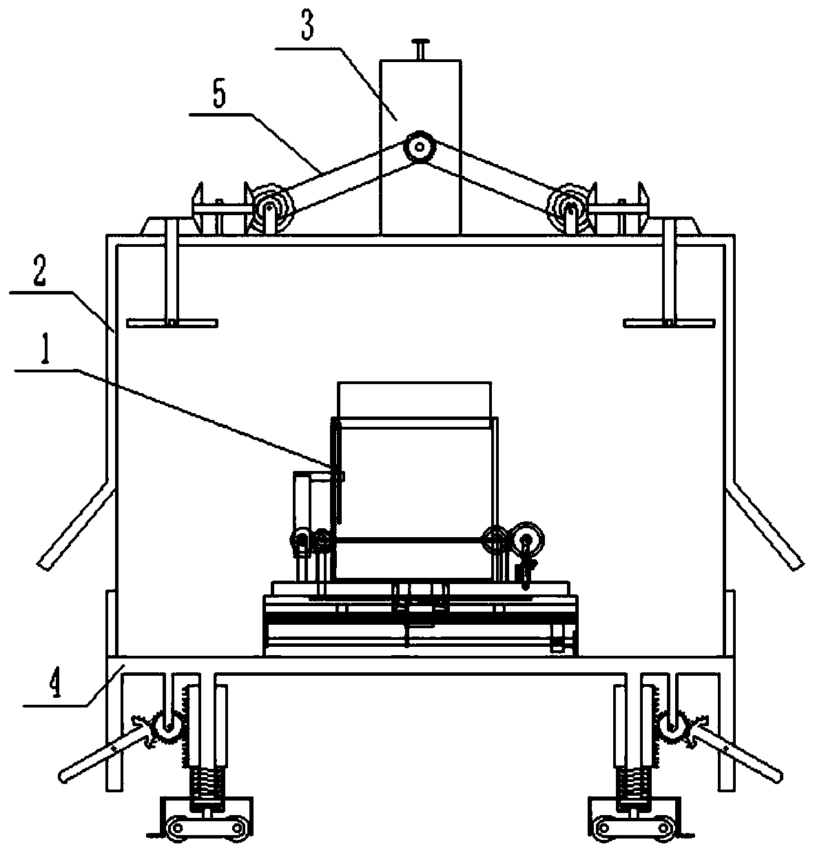
[0046] Combine below Figure 1-28 To illustrate this embodiment, a multi-angle adjustable laser cutting machine includes an angle fixing assembly 1, a heat dissipation assembly 2, a speed control device 3, a chassis assembly 4 and two connecting belts 5. The angle fixing assembly 1 Fixedly connected to the upper end of the chassis assembly 4, the fixed angle assembly 1 is arranged at the inner end of the heat dissipation assembly 2, the heat dissipation assembly 2 is fixedly connected to the upper end of the chassis assembly 4, and the speed regulating device 3 is fixedly connected to the heat dissipation assembly At the upper end of the body 2, two connecting belts 5 are connected between the speed regulating device 3 and the heat dissipation assembly 2.
specific Embodiment approach 2
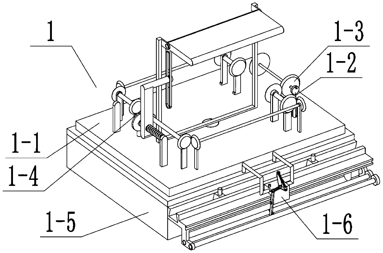
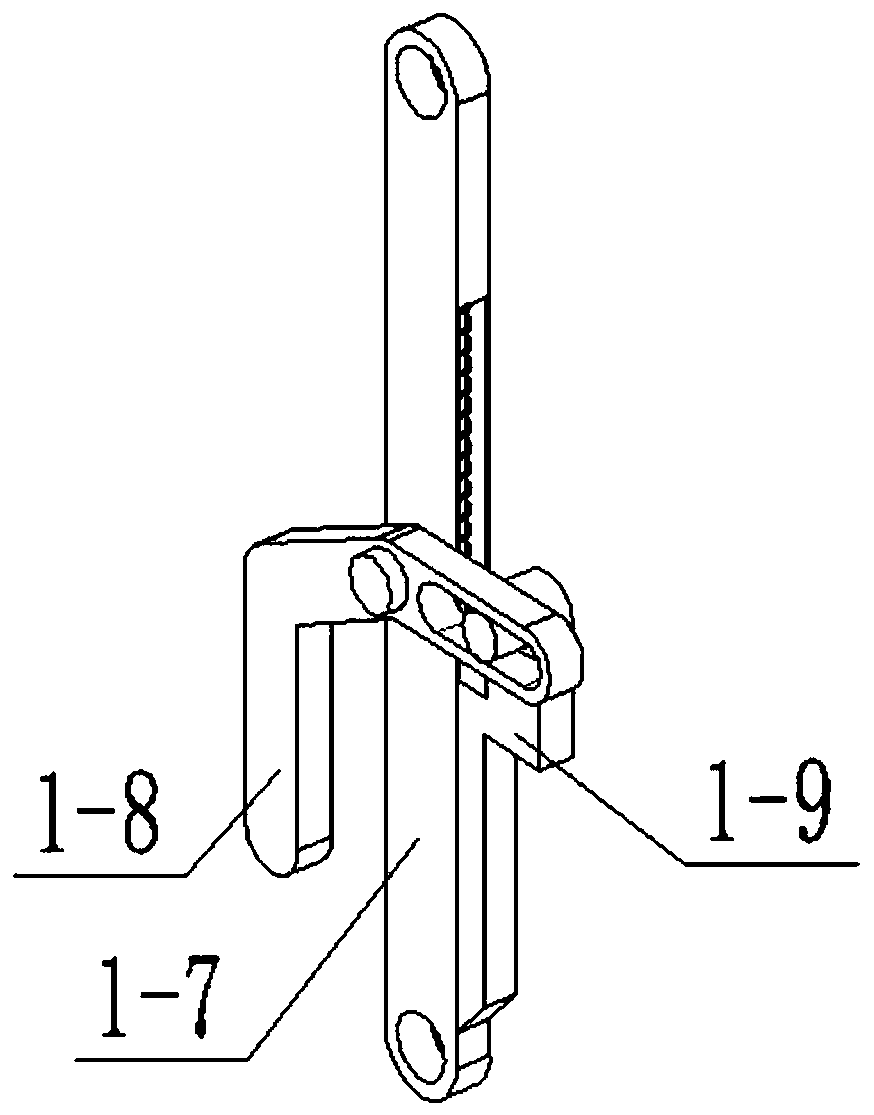
[0048] Combine below Figure 1-28Describe this embodiment. This embodiment will further explain Embodiment 1. The angle fixing assembly 1 includes a fixed plate assembly 1-1, a driving rod assembly 1-2, a driving bevel gear assembly 1-3, and a middle end transmission assembly 1. -4. Bottom plate combination 1-5, reversing device 1-6, driving rod 1-7, grip rod 1-8, driving clamping rod 1-9, driving rod rotating column 1-10, inner end sliding column 1 -11, side wall sliding cavity 1-12, inner push spring 1-13, fixed plate body 1-14, bottom plate body 1-15, bevel tooth 1-16, rotating rod 1-17, straight tooth 1 -18, bevel teeth 2 1-19, rotating rod 2 1-20, bevel teeth 3 1-21, bevel teeth 4 1-22, rotating rod 3 1-23, bevel teeth 4 1-24, bevel teeth 5 1- 25. Rotating rod four 1-26, bevel teeth six 1-27, bevel teeth seven 1-28, rotating rod five 1-29, bevel teeth eight 1-30, bevel teeth nine 1-31, rotating rod six 1-32 , Bevel tooth ten 1-33, straight tooth two 1-34, side wall driv...
specific Embodiment approach 3
[0051] Combine below Figure 1-28 Describe this embodiment, this embodiment will further explain Embodiment 1, the heat dissipation assembly 2 includes a heat dissipation outer frame 2-1, a transmission assembly 2-2, a heat dissipation outer frame body 2-4, a heat dissipation hole 2-5, an upload Moving bevel gear one 2-6, upper rotating rod 2-7, fan blade 2-8, upper side hinged frame one 2-9, upper side hinged frame two 2-10, upper transmission rotating rod one 2-11, upper transmission Bevel teeth two 2-12, upper transmission bevel teeth three 2-13, upper transmission bevel teeth four 2-14, upper end belt pulley 2-15 and upper transmission rotating rod two 2-16, the transmission combination 2-2 and heat dissipation The outer frame 2-1 is rotationally connected, the heat dissipation holes 2-5 are arranged on the side wall of the heat dissipation outer frame body 2-4, the upper rotating rod 2-7 is rotationally connected with the heat dissipation outer frame body 2-4, and the upp...
PUM
 Abstract
Description
Claims
Application Information
 - R&D
- Intellectual Property
- Life Sciences
- Materials
- Tech Scout
- Unparalleled Data Quality
- Higher Quality Content
- 60% Fewer Hallucinations
Browse by: Latest US Patents, China's latest patents, Technical Efficacy Thesaurus, Application Domain, Technology Topic, Popular Technical Reports.
© 2025 PatSnap. All rights reserved.Legal|Privacy policy|Modern Slavery Act Transparency Statement|Sitemap|About US| Contact US: help@patsnap.com