
DD motor nut rotary feeding device

A technology of nut rotation and feeding device, which is applied in transmission devices, large fixed members, belts/chains/gears, etc. It can solve the problems of low transmission accuracy and achieve the effects of convenient installation, stable driving and reduced driving stroke

Pending Publication Date: 2019-08-30
上海玖蓥智能科技有限公司
View PDF0 Cites 1 Cited by
  • Summary
  • Abstract
  • Description
  • Claims
  • Application Information

AI Technical Summary

Problems solved by technology

[0005] Aiming at the technical problem of low transmission accuracy caused by the shaking of the fixed screw rod proposed in the background technology, the present invention aims to provide a DD motor nut rotary feeding device. Rotate on the rod, and drive the driving part and the feed table structure to move synchronously on the track structure, so as to avoid the vibration problem of long stroke, so as to achieve the purpose of improving the transmission accuracy

Method used

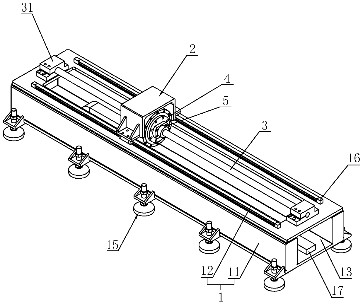

Image

  • DD motor nut rotary feeding device
  • DD motor nut rotary feeding device
  • DD motor nut rotary feeding device

Examples


Embodiment 1

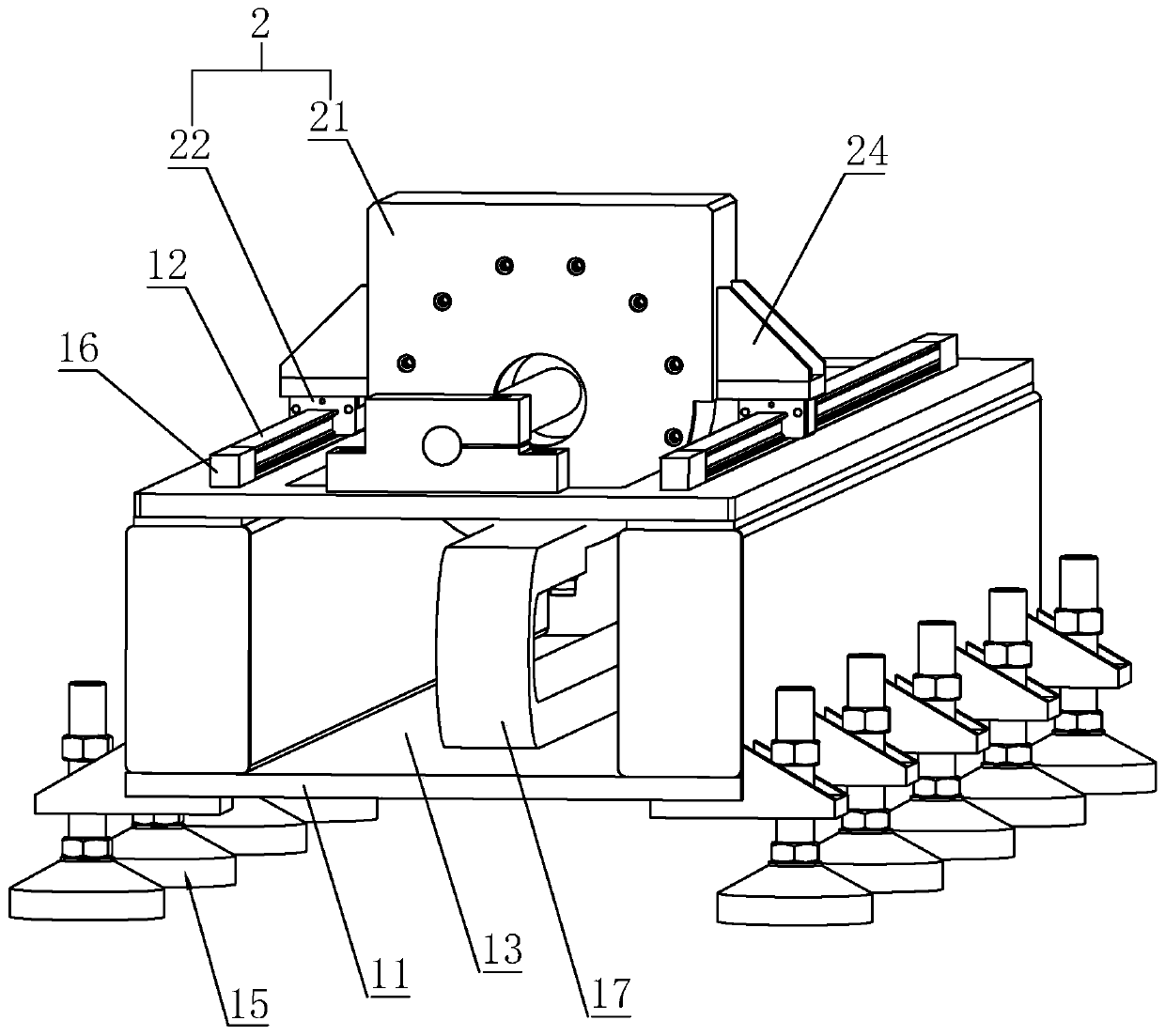
[0040] Refer to background technology figure 1 , the main technical point of the present invention is to integrate the motor 031 and the worktable 02 together, reduce the driving stroke between the motor 031 and the worktable 02, avoid the vibration of the screw rod 033, and improve the driving stability. The specific implementation structure is a DD motor nut rotary feeding device, combined with figure 2 and image 3 It can be seen that it includes a track structure 1 , a feed table structure 2 , a fixed screw rod 3 and a driving structure sleeved on the fixed screw rod 3 for driving the feed table structure 2 to move. The feed table structure 2 is slidably installed on the track structure 1 , and the drive structure is installed in the feed table structure 2 and fixed thereto, so as to realize the integration between the drive structure and the feed table structure 2 . At the same time, the drive structure drives itself to move back and forth along the fixed screw rod 3, ...

Embodiment 2

[0050] The difference between this embodiment and Embodiment 1 is that an insulating electrical tank is provided in the installation groove 13, and an electrical connecting piece is provided at the power-connecting end of the driving member 4, and the electrical connecting piece is slidably connected in the insulating electrical tank to continuously receive electricity. . Wherein, the insulating tank is made of insulating materials such as plastic materials, and at the same time, a conductive piece is arranged in the insulating tank, and the connecting piece is always slidingly connected with the connecting piece when sliding, so as to keep the driving member 4 conveniently connected to electricity.


PUM


Abstract

The invention relates to the technical field of feeding transmission systems and discloses a DD motor nut rotary feeding device which solves the technical problem that due to shaking of a current fixing screw rod, transmission precision is low. The DD motor nut rotary feeding device comprises a track structure, a feeding table structure and a fixing screw rod. The feeding table structure is installed on the track structure in a sliding manner. The two ends of the fixing screw rod are fixed to the two ends of the track structure correspondingly. The fixing screw rod does not rotate. The fixingscrew rod is provided with a drive structure used for driving the feeding table structure to move in a sleeved manner. The drive structure comprises a drive part for providing torque, and a nut-like part rotating forward or reversely under driving of the drive part. The nut-like part is in thread fitting with the fixing screw rod. The drive part and the feeding table structure are mutually fixed.According to the technical scheme, the fixing screw rod is arranged not to rotate, the drive part drives the nut-like part to rotate on the fixing screw rod, the drive part and the feeding table structure are driven to move on the track structure synchronously, the problem of long shaking is avoided, and thus the purpose of improving the transmission precision is achieved.

Description

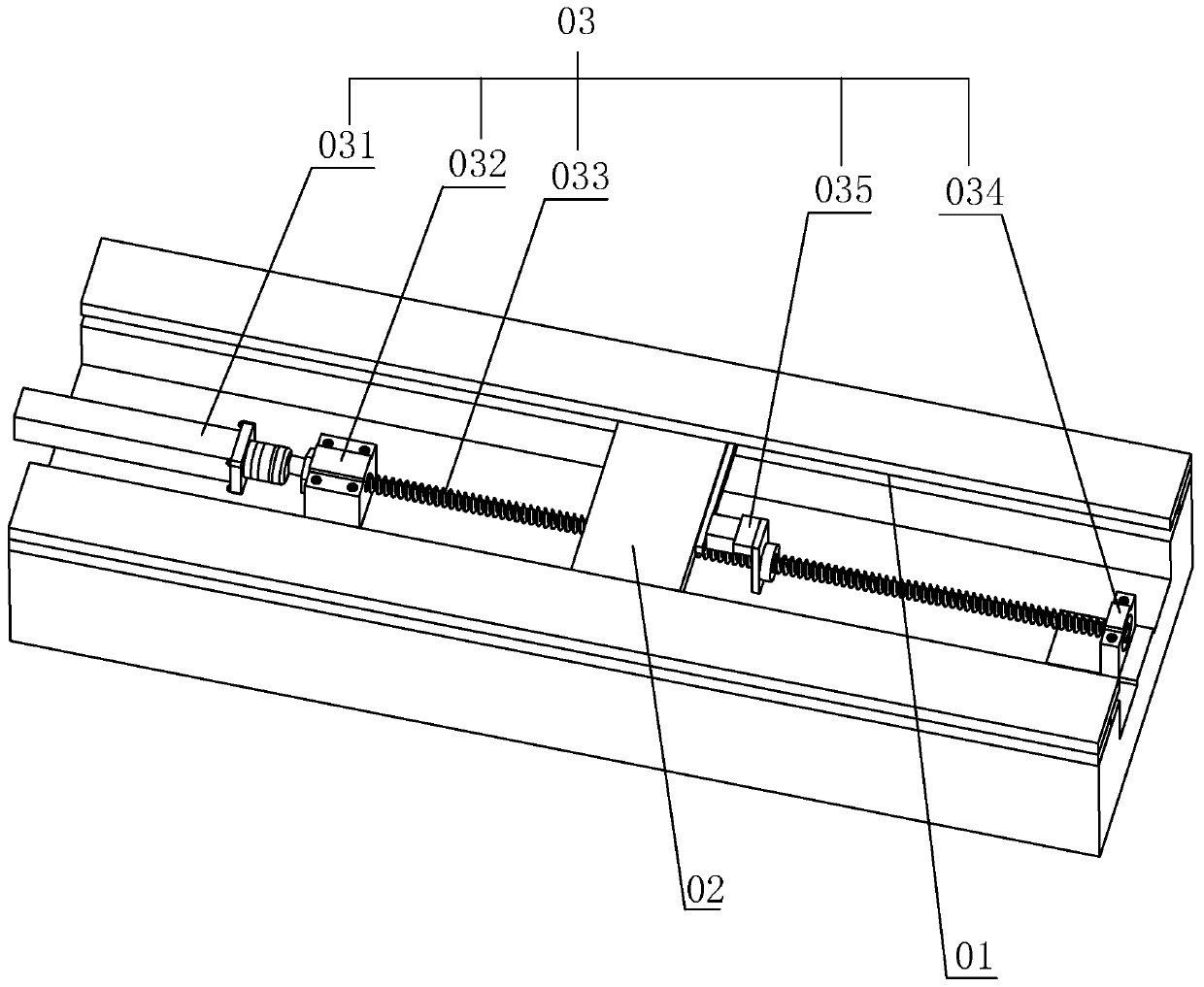
technical field [0001] The invention relates to the technical field of feed transmission system, more specifically, it relates to a DD motor nut rotary feed device. Background technique [0002] The feed transmission system is the entire mechanical transmission chain that converts the operation (usually rotation) of the motor into the linear feed motion of the machine table. The final coordinate position accuracy and contour accuracy of the workpiece are related to the geometric accuracy and transmission of the transmission structure of the machine tool. Accuracy, sensitivity and stability are closely related. [0003] Such as figure 1 Shown is a feed drive system in the prior art, which includes a guide rail 01 , a worktable 02 slidably mounted on the guide rail 01 , and a driving device 03 for driving the worktable 02 to slide. Wherein, the driving device 03 includes a motor 031 , a mounting bearing 032 , a screw rod 033 , a mounting base 034 and a connecting block 035 ....

Claims


Application Information

Patent Timeline
Patent Type & Authority Applications(China)
IPC IPC(8): B23Q1/25F16H25/20
CPCB23Q1/25F16H25/20
Inventor 胡文强
Owner 上海玖蓥智能科技有限公司
Learn More