Building load bearing steel bar abutting joint device

A technology of docking device and steel bar, which is applied in the direction of building structure, building, building components, etc., can solve the problems of low construction efficiency, high energy consumption, etc., and achieve the effect of improving efficiency and fixing effect

Active Publication Date: 2019-08-30
湖南煜翔建设工程有限公司
View PDF5 Cites 4 Cited by
  • Summary
  • Abstract
  • Description
  • Claims
  • Application Information

AI Technical Summary

Problems solved by technology

[0004] A load-bearing steel bar docking device for building loads, which can quickly, efficiently and labor-savingly butt joint steel bars through the docking device, so as to solve the problems of low construction efficiency and high energy consumption in the existing steel bar mechanical sleeve docking

Method used


Image

  • Building load bearing steel bar abutting joint device
  • Building load bearing steel bar abutting joint device
  • Building load bearing steel bar abutting joint device

Examples


Embodiment Construction

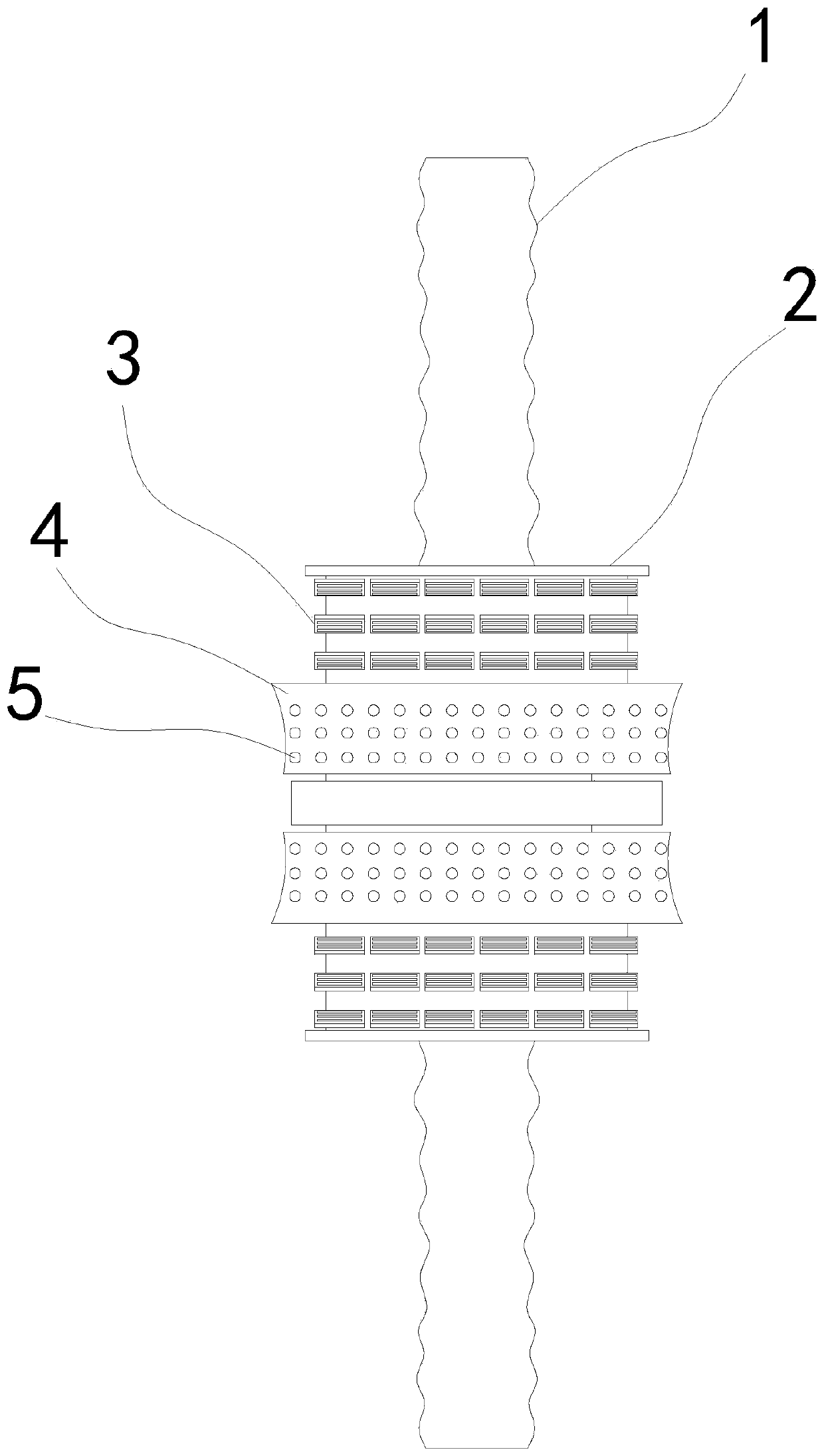
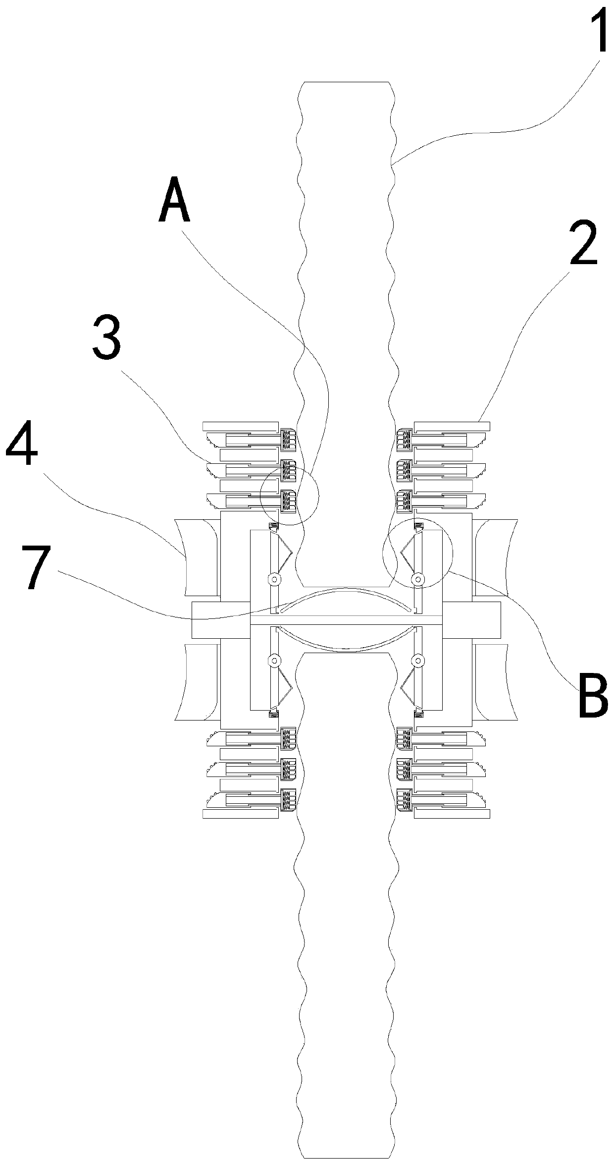
[0026] see Figures 1 to 8 , a schematic diagram of a planar structure and a schematic diagram of a three-dimensional structure of a load-bearing steel bar butt joint device for building loads.

[0027] A load-bearing butt joint device for building load-bearing steel bars, comprising a steel bar 1 and a butt joint device 2, a joint joint device 2 is fixedly connected to the steel bar 1, a moving ring 4 is sleeved on the outside of the joint joint device 2, and a lower pressing block 3 is movably installed inside the joint joint device 2 .

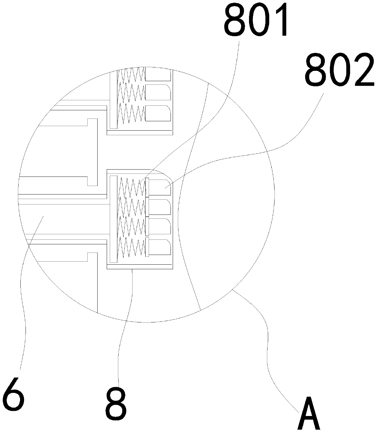
[0028] In a specific implementation, one end of the lower pressing block 3 facing the reinforcing bar 1 is fixedly connected with a connecting rod 6, and one end of the connecting rod 6 facing the reinforcing bar 1 is movably sleeved with a fixed cavity 8, and the end of the fixing cavity 8 facing the reinforcing bar is open, so that When the moving ring 4 moves the lower pressing block 3 downwards, the fixing cavity 8 can fit the protrudi...


PUM


Abstract

The invention relates to the abutting joint field of building materials, in particular to a building load bearing steel bar abutting joint device. The building load bearing steel bar abutting joint device includes steel bars and an abutting joint device bodies, wherein the abutting joint device bodies are fixedly connected to the steel bars, mobile rings sleeve outside the abutting joint device bodies, and downward pressure blocks are movably installed inside the abutting joint device bodies. The top ends of the downward pressure blocks are arranged as arcs, and the horizontal part is formed above the arcs, so that when the mobile rings move upwards, through upward inclined arcs arranged outside the mobile rings, anti-skid raised blocks uniformly distributed on the arcs and outward inclined arcs arranged at the upper ends of the interior of the mobile rings, the mobile rings are enabled to enable the downward pressure blocks to move downwards to fix the steel bars in a more labor-saving mode, and meanwhile, through the horizontal part, the contact area between the downward pressure blocks and the mobile rings is increased after the downward pressure blocks are subjected to downwardpressure, so that the mobile rings cannot slide downwards. Then, the mobile rings can be further enabled to be labor-saving by the embedded combination of rotating wheels movably installed at the topends of the downward pressure blocks and fixed grooves formed in the mobile rings, wherein the rotating wheels are provided with an outer convex parts and inner concave part which are arranged in a staggered mode, and the fixed grooves are formed in a concave interval mode.

Description

technical field [0001] The invention relates to the field of butt joints of building materials, in particular to a butt joint device for building load-bearing steel bars. Background technique [0002] In the construction process of existing reinforced concrete structures, the commonly used connection methods of steel bars generally include bundling, welding and mechanical sleeve connection. The mechanical sleeve connection joint of steel bars can also improve the toughness of steel bars without destroying the toughness of steel bars. Connection strength, so mechanical sleeve connections are relatively more commonly used. [0003] However, the existing mechanical sleeve connection operation is cumbersome and this method requires manpower to apply torque with a torque wrench on site, which makes the connection between the steel bar and the mechanical sleeve time-consuming and laborious, and the efficiency is low, which cannot meet the current needs of rapid and high-speed cons...

Claims


Application Information

Patent Timeline
Patent Type & Authority Applications(China)
IPC IPC(8): E04C5/16
CPCE04C5/163
Inventor 黄志勤
Owner 湖南煜翔建设工程有限公司
Why Eureka
Try Eureka