
Heating pipeline draining device

A technology for drainage devices and heating pipes, applied in the direction of pipe elements, pipes/pipe joints/pipe fittings, mechanical equipment, etc., can solve the problems of poor drainage effect, environmental impact, poor sewage treatment, etc., to improve the filtering effect. , easy to carry, small size of the device

Inactive Publication Date: 2019-08-30
青岛宝能管道股份有限公司
View PDF5 Cites 0 Cited by
  • Summary
  • Abstract
  • Description
  • Claims
  • Application Information

AI Technical Summary

Problems solved by technology

When the heating pipe drains, due to the large impact force, if it is not handled properly, it will affect the surrounding environment
If the pipeline is directly used for drainage, the drainage effect is not good, and the sewage is not easy to treat

Method used


Image

  • Heating pipeline draining device

Examples


Embodiment Construction

[0015] Below in conjunction with accompanying drawing and specific embodiment the present invention is described in further detail:

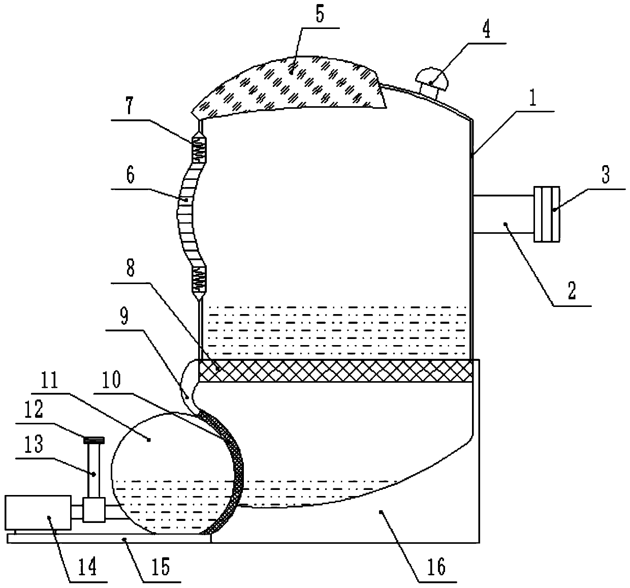
[0016] Such as figure 1 As shown, a heating pipe drainage device includes a cavity 1 , a buffer plate 6 , a coarse filter 8 , a fine filter 10 , a storage tank 11 and a slow flow chamber 16 .

[0017] A water inlet pipe 2 is provided on one side of the chamber body 1, and a water inlet pipe joint 3 is installed at the end of the water inlet pipe 2. One end of the water inlet pipe 2 is connected to the drain of the heating pipe, and the heating pipe and the water inlet pipe 2 are connected through the water inlet pipe joint 3. . A buffer plate 6 is installed on the other side of the cavity 1, and the buffer plate 6 is installed in alignment with the water inlet pipe 2, and the buffer plate 6 can buffer the impulsive force of the water rushing in from the heating pipeline. The outer end of the buffer plate 6 is connected to the wall surface of t...


PUM


Abstract

The invention discloses a heating pipeline draining device. A water inlet pipe is arranged on one side of a cavity, and a buffering plate is installed on the other side of the cavity. The buffering plate and the water inlet pipe are aligned to be installed. The outer end of the buffering plate is connected with the wall face of the cavity through a shock absorber, and the lower end of the cavity is erected above a slow flowing bin. A rough filtering net is installed at the connecting position of the cavity and the slow flowing bin. The bottom of an inner bin of the slow flowing bin is in an arc shape with one high side and one low side. A fine filtering net is arranged on the arc low side and is installed on a baffle. The baffle is installed on one side of the slow flowing bin. The fine filtering net is of arc design, and a storage tank is installed on the arc inner side of the fine filtering net. One side of the storage tank is provided and connected with a water outlet pipe and a water pump. By means of the heating pipeline draining device, impulse force of water flow discharged from a heating pipe is reduced through the buffering plate, the water flow is filtered after being slowed down, two-layer filtering is achieved, the filtering is improved, and in addition, the water flow is discharged to the designated position through the water pump. The heating pipeline draining device is simple in structure, simple in work principle, small in size, easy to carry and suitable for various occasions.

Description

technical field [0001] The invention relates to the field of heating pipelines, in particular to a drainage device for heating pipelines. Background technique [0002] When the water in the heating pipeline needs to be changed, the water in the heating pipeline needs to be discharged. After the water in the heating pipe is left for a long time, sundries will appear. In the drainage, it is necessary to remove the sundries to prevent pollution of the environment. When the heating pipe drains, due to the large impact force, if it is not handled properly, it will have an impact on the surrounding environment. If pipes are used for drainage directly, the drainage effect is not good, and the sewage is not easy to handle. For this reason, propose a kind of heating pipeline drainage device. Contents of the invention [0003] In order to solve the above existing problems, the present invention provides a heating pipe drainage device, which can solve the problems mentioned in th...

Claims


Application Information

Patent Timeline
Patent Type & Authority Applications(China)
IPC IPC(8): F16L55/07
CPCF16L55/07
Inventor 梁冲孙胜臣亓健
Owner 青岛宝能管道股份有限公司
Learn More