
An exhaust device for hydraulic jump trowel in circulating water tank and its application

A technology of circulating water tank and exhaust device, which is used in measuring devices, testing of machine/structural components, instruments, etc., can solve problems such as adverse effects of equipment, and achieve the effects of smoothing water waves, suppressing water waves, and removing air bubbles.

Active Publication Date: 2021-02-12
708TH RES INST OF CSSC
View PDF7 Cites 0 Cited by
  • Summary
  • Abstract
  • Description
  • Claims
  • Application Information

AI Technical Summary

Problems solved by technology

At present, the inventor has invented a new type of hydraulic trowel, which can not only obtain high-quality high-speed or ultra-high-speed free liquid relatively easily The circulating water tank on the surface has the characteristics of low manufacturing and operating costs, energy saving, and environmental protection. , a large number of air bubbles will be brought into the downstream water flow on the lower plane of the water dividing plate, so that there will be a large number of air bubbles in the water flow (main flow) at the lower plane of the water dividing plate. The impact is also extremely unfavorable

Method used


Image

  • An exhaust device for hydraulic jump trowel in circulating water tank and its application
  • An exhaust device for hydraulic jump trowel in circulating water tank and its application
  • An exhaust device for hydraulic jump trowel in circulating water tank and its application

Examples


Embodiment 1

[0027] This embodiment relates to an exhaust device of a preferred structural form for a hydraulic jump trowel in a circulating water tank.

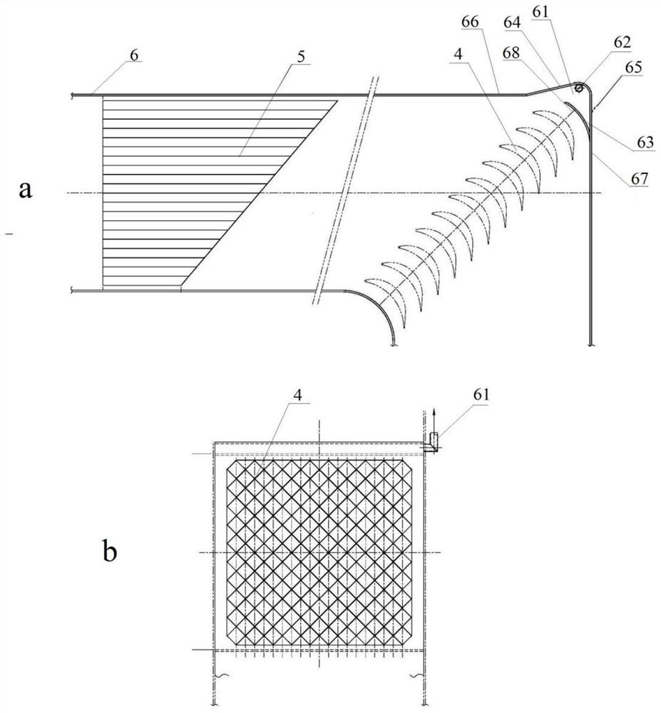
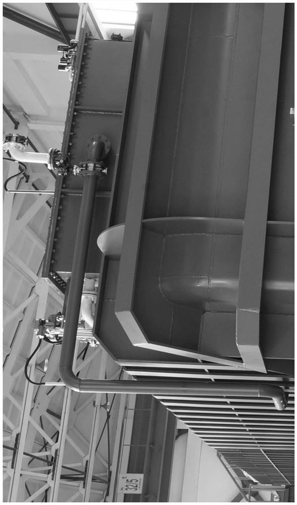
[0028] Such as Figure 1 ~ Figure 3 As shown, the exhaust device for the hydraulic jump trowel of the circulating water tank provided by this embodiment is generally composed of the grille 5 and the corner structure at the first elbow 68 of the water dividing plate arranged behind the grille 5 61, and the exhaust pipeline arranged between the two sides of the first elbow 68 of the water diversion plate and the gas collection box on the upper part of the tank body, through the above structure, the air bubbles are separated through the pipeline and collected through the exhaust pipeline Arranged on the air collecting box on the upper part of the tank body, so as to achieve the purpose of eliminating air bubbles in the water flow.

[0029] In this embodiment, the hydraulic jump trowel is located downstream of the test section 8, and the en...

Embodiment 2

[0033] This embodiment is a circulating water tank hydraulic system containing the free liquid surface of the exhaust device for the hydraulic jump trowel of the circulating water tank described in embodiment 1.

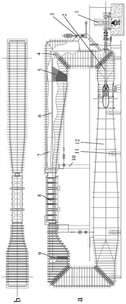
[0034] Such as figure 2 As shown, the hydraulic system of the circulating water tank includes a main motor 1 connected by pipelines, a main circulation pump 2, an auxiliary pump 3, a corner deflector 4, a grille 5, a water dividing plate 6, an energy dissipation plate 7, a test section 8, The honeycomb 9, the tank body 12; the water dividing plate 6 is provided with a corner structure 61 for collecting air bubbles at the first elbow 68 of the water dividing plate; the water tank body 12 is installed on the base 11, and passes through the column 10 and test A fixed connection is made downstream of section 8. The connection methods of the above-mentioned devices can be arranged with reference to conventional methods in the field.

[0035] It can be seen from the abo...


PUM


Abstract

The invention relates to an exhaust device for a hydraulic jump trowel of a circulating water tank, which includes a water diversion plate and a grille located in the hydraulic jump trowel, and the water diversion plate has a first elbow of the water diversion plate; wherein, The first elbow is set as a protruding corner structure, the inner side of the corner structure is an arc wall with an opening, the first side of the corner structure has a certain angle with the lateral side of the first elbow, and the corner structure The second side is parallel to and extended to the vertical side of the first elbow, the opening of the arc wall is close to the first side, and an exhaust port is provided at the end of the corner structure. The present invention also relates to a circulating water tank hydraulic system with the free liquid surface of the above-mentioned exhaust device. The exhaust device of the present invention arranges a special grid array to discharge and separate air bubbles from the water flow, and arranges a special corner structure at the first elbow of the water separating plate behind the grid array to separate the air bubbles through the pipeline and It is collected into the air collection box through the exhaust pipeline, so as to achieve the purpose of eliminating air bubbles in the water flow.

Description

technical field [0001] The invention belongs to the technical field of ship testing, and in particular relates to a circulating water tank hydraulic system used for an exhaust device of a hydraulic jump trowel of a circulating water tank and a free liquid surface thereof. Background technique [0002] The circulating water tank is a device specially engaged in the performance research and maneuverability research of ship propellers. Contrary to the drag tank, in the circulating tank, the model is fixed, the water flow circulates in the tank, and the water flow in the test working section is guaranteed to be uniform. Most of the ordinary circulating water tanks with free surface at home and abroad are usually low-speed (Fr number is less than 1), and for circulating water tanks with high-speed free surface, generally a large water tank is arranged after the test section The technical scheme is to realize the requirement of maintaining the free liquid surface in the test work...

Claims


Application Information

Patent Timeline
Patent Type & Authority Patents(China)
IPC IPC(8): G01M10/00
CPCG01M10/00
Inventor 夏丁良翟志红俞瑜俞宾梁珺
Owner 708TH RES INST OF CSSC
Learn More