
Grease depositing tank

A sedimentation tank and oil technology, applied in the direction of oil/fat refining, fat production, etc., can solve the problems of filter plate clogging, reduce the quality of pepper oil, equipment can not be used normally, etc., and achieve the effect of increasing the contact area.

Pending Publication Date: 2022-04-08
CHONGQING ZHIQINGYANG GREASE CO LTD
View PDF0 Cites 0 Cited by
  • Summary
  • Abstract
  • Description
  • Claims
  • Application Information

AI Technical Summary

Problems solved by technology

The oil precipitation device in the prior art is used to filter and precipitate the pepper oil, but the existing oil precipitation device is generally a first-stage filter, and the small impurities contained in it are still in the pepper oil, which reduces the quality of the pepper oil
At the same time, the filter plate is easily blocked by impurities, causing the equipment to be unable to use normally and reducing the utilization efficiency of the equipment

Method used


Image

  • Grease depositing tank
  • Grease depositing tank
  • Grease depositing tank

Examples


Embodiment 1

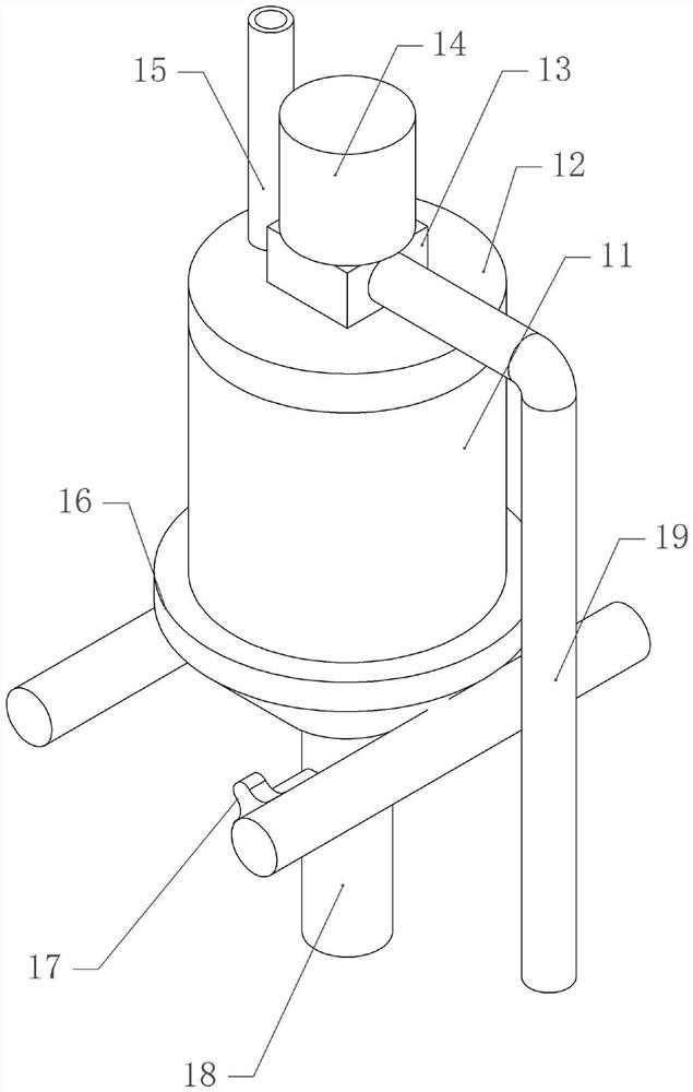
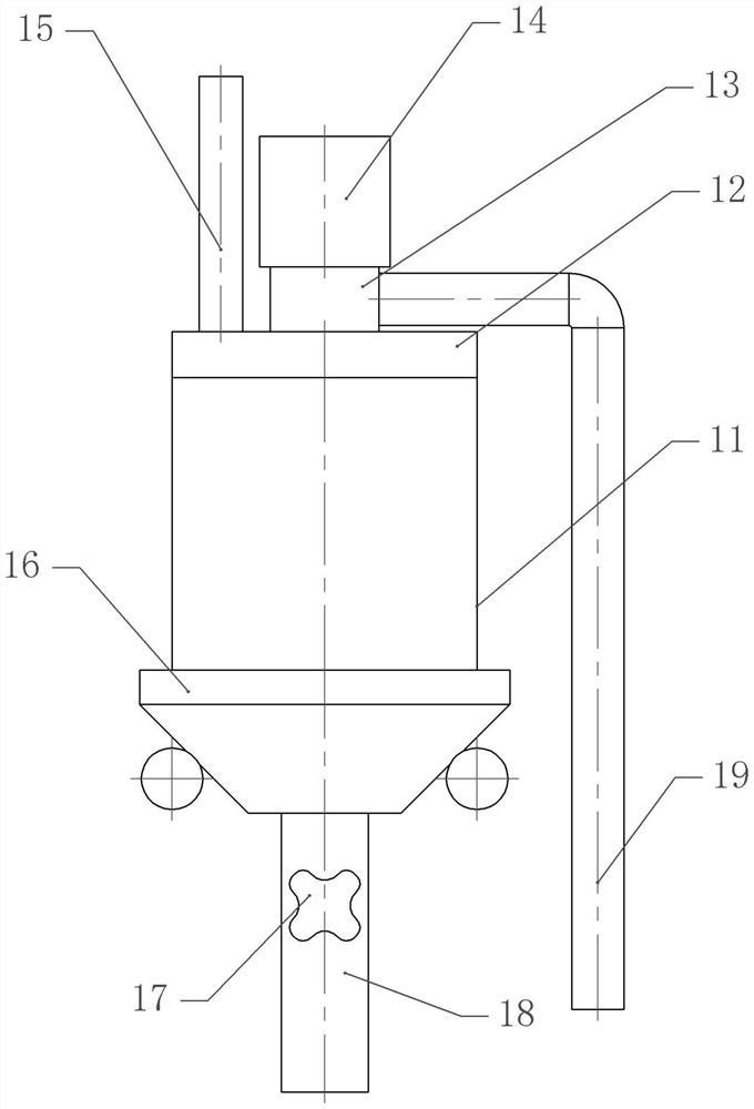
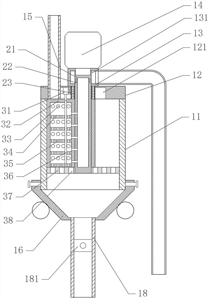
[0036] A kind of grease sedimentation tank, as attached figure 1 , attached figure 2 And attached image 3 As shown, it includes a frame and a tank body 11 fixed by bolts on the frame, the upper opening of the tank body 11, and a cover body 12 for closing the opening is fixed by bolts on the tank body 11.

[0037] In this embodiment, the feed pipe 15 is fixed with bolts on the cover body 12, the support part 13 is fixed on the cover body 12, and the support part 13 has a cavity 131, and also includes a waste discharge structure, which includes a negative pressure pump And the waste discharge pipe communicated with the negative pressure pump, the waste discharge pipe communicates with the cavity 131 .

[0038] Bolts on the support part 13 are fixed with a driving part, the driving part is a motor 14, the output shaft of the driving part is coaxially fixedly connected with a rotating shaft 21 which is rotatably connected with the cover plate, and a ball bearing 23 is set on t...

Embodiment 2

[0047] The difference between embodiment two and embodiment one is that, as attached Figure 4 As shown, the bottom of the rotating shaft 21 is fixed with a permeable layer 46, and the bottom of the permeable layer 46 is provided with a closing plate 44. The closing plate 44 is rotatably connected with the tank body 11 by a torsion spring, and the bottom of the closing plate 44 is hinged with a connecting rod 42. The rod 42 is hinged with the spoiler 181, and the discharge pipe is fixedly connected with a guide pipe 43, and the guide pipe 43 is vertically slidably connected with the connecting pipe.

[0048] In this embodiment, both sides of the closing plate 44 are provided with a second arc-shaped surface 45, and both sides of the spoiler 181 are provided with a first arc-shaped surface 41, so that the closing plate 44 is in line-surface contact with the tank body 11 , can reduce the frictional resistance between the closing plate 44 , the spoiler 181 and the side wall, so t...


PUM


Abstract

The invention belongs to the technical field of grease precipitation equipment, and provides a grease precipitation tank which comprises a tank body with an opening in the upper part and a cover body for sealing the tank body, a supporting part and a driving part fixed on the supporting part are fixed on the tank body, a rotating shaft positioned in the tank body is fixed on an output shaft of the driving part, a stirring part is fixed on the rotating shaft, a plurality of through holes are formed in the stirring part, a plurality of filtering plates are vertically arranged in the stirring part, and the apertures of the filtering holes in the plurality of filtering plates are sequentially reduced from top to bottom; a partition plate fixedly connected with the tank body is arranged below the stirring part, and a secondary hole is formed in the partition plate; and a discharging structure is arranged below the partition plate. According to the present invention, the multi-stage filtration is performed on the zanthoxylum oil so as to remove the impurities in the zanthoxylum oil, and the zanthoxylum oil is precipitated so as to improve the quality of the zanthoxylum oil.

Description

technical field [0001] The invention belongs to the technical field of grease precipitation equipment, and in particular relates to a grease precipitation tank. Background technique [0002] Zanthoxylum bungeanum oil is a fragrant edible vegetable oil extracted from Zanthoxylum bungeanum. During the production process, Zanthoxylum bungeanum oil will go through many processes and it is not easy to obtain. [0003] For example: pepper oil needs to be filtered and precipitated to purify the oil step by step to obtain usable pepper oil. The oil precipitating device in the prior art is used to filter and precipitate the pepper oil, but the existing oil precipitating device is generally a first-stage filter, and the small impurities contained therein are still in the pepper oil, which reduces the quality of the pepper oil. At the same time, the filter plate is easily blocked by impurities, causing the equipment to be unable to use normally and reducing the utilization efficiency ...

Claims


Application Information

Patent Timeline
Patent Type & Authority Applications(China)
IPC IPC(8): C11B3/00C11B3/16
Inventor 吕智彪
Owner CHONGQING ZHIQINGYANG GREASE CO LTD
Learn More