Soil heavy metal detection systems

A detection system and heavy metal technology, which is applied in the direction of measuring devices, instruments, scientific instruments, etc., can solve the problems of large resource consumption and slow speed of soil heavy metal detection technology, and achieve the effect of reducing energy consumption and saving resources

Pending Publication Date: 2019-08-30
鲁匡正
View PDF0 Cites 4 Cited by
  • Summary
  • Abstract
  • Description
  • Claims
  • Application Information

AI Technical Summary

Problems solved by technology

[0003] For this reason, the embodiment of the present invention provides a soil heavy metal detection system to solve the problems of slow speed and large resource consumption of the existing soil heavy metal detection technology

Method used


Image

  • Soil heavy metal detection systems
  • Soil heavy metal detection systems
  • Soil heavy metal detection systems

Examples


Embodiment 1

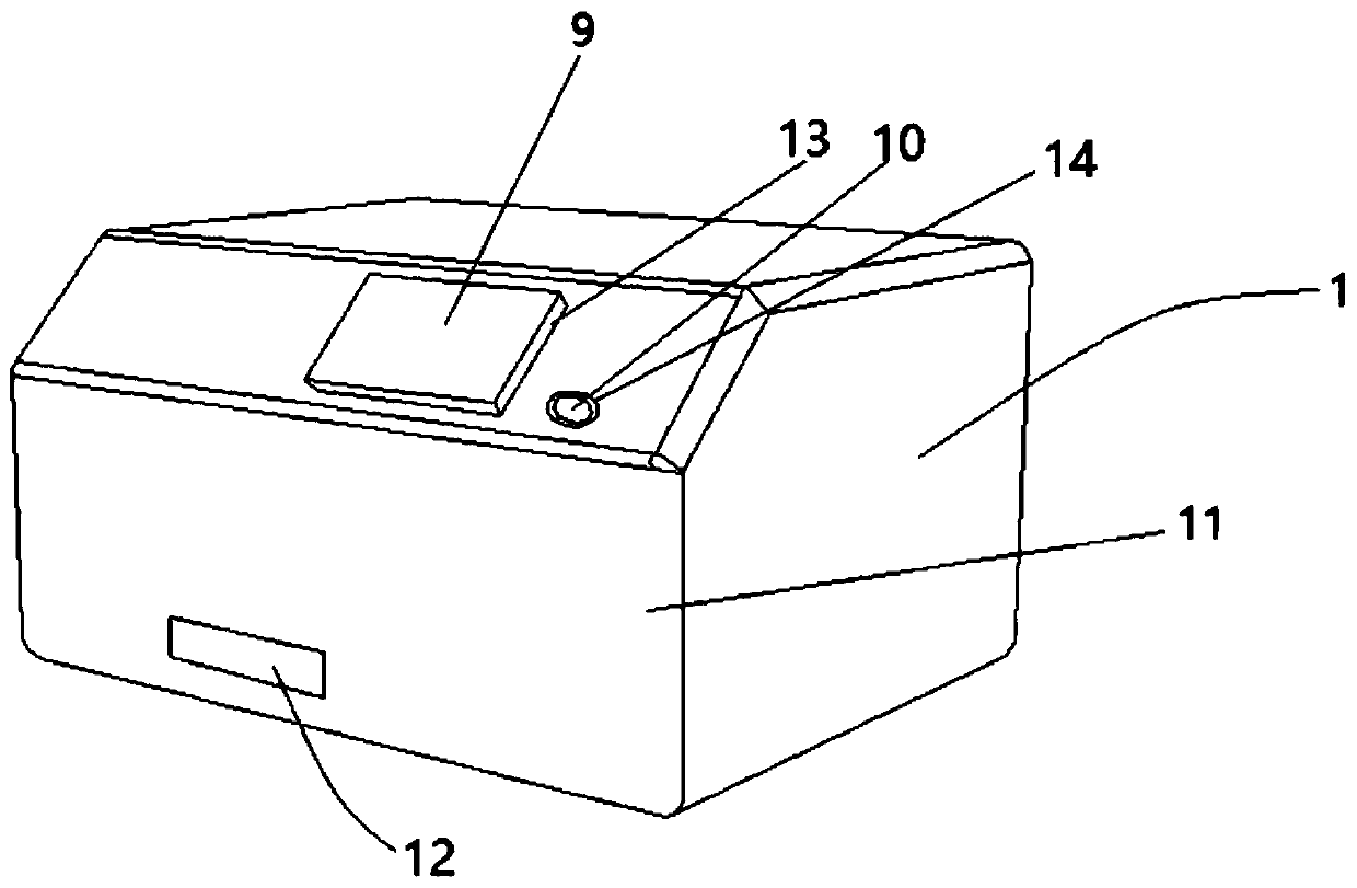
[0053] see Figure 1~6 , a soil heavy metal detection system provided by the present invention, the system includes: a chassis 1, the lower part of the front panel 11 of the chassis 1 is provided with a sample tray outlet 12; 1. Two Y-axis linear slides 21 on the inner surface of the bottom plate. The two Y-axis linear slides 21 are respectively connected to a Y-axis drive motor 22; The X-axis linear slide 31 is perpendicular to each other. The two ends of the bottom surface of the X-axis linear slide 31 are respectively erected on the Y-axis slide 211 of a Y-axis linear slide 21. The X-axis linear slide 31 is connected by transmission. There is an X-axis driving motor 32; the Z-axis moving assembly 4 includes a Z-axis linear slide table 41 vertically arranged on the upper surface of the X-axis slide seat 311 of the X-axis linear slide table 31, and the Z-axis linear slide table The Z-axis sliding seat 411 of 41 is set towards the front panel 11 of the box body 1, and the Z-a...

Embodiment 2

[0077] A pallet moving assembly 20 is mounted on the inner surface of the bottom plate of the chassis 1 between the two Y-axis linear slides 21. The pallet moving assembly 20 includes a pallet linear slide 201, and the pallet linear slide 201 is along the length of the Y-axis linear slide 21. Direction setting, the tray linear slide 201 is connected with a tray drive motor 202; the bottom surface of the sample tray 6 is set on the tray slide 203 of the tray linear slide 201; the tray drive motor 202 communicates with the control assembly 8 And it is electrically connected with the power supply unit 7 .

[0078] Further, a position sensor (not shown) is provided at the end of the tray linear slide 201 close to the sample tray outlet 12 , and the position sensor is connected to the control assembly 8 in communication.

[0079] The design of the tray moving component 20 can realize the front and rear sliding of the sample tray 6 inside the cabinet 1, realize the automatic transmi...

Embodiment 3

[0083] A vibration-damping support seat 30 is vertically provided at both ends of the bottom surface of the Y-axis linear slide 21 in the longitudinal direction.

[0084] The design of the vibration-damping support seat 30 can provide vibration-damping support for the Y-axis moving assembly 2, so that the Y-axis moving assembly 2 can strongly support the X-axis moving assembly 3 and the Z-axis moving assembly 4, thereby improving the service life.

[0085] All the other are with embodiment 1.


PUM


Abstract

The embodiments of the invention disclose soil heavy metal detection systems. A system comprises a case, wherein a sample tray outlet is set at a lower part of a front panel of the case; Y-axis movingassemblies which comprise two Y-axis straight sliding tables; an X-axis moving assembly which comprises an X-axis straight sliding table, wherein the X-axis straight sliding table is erected on Y-axis sliding bases; a Z-axis moving assembly which comprises a Z-axis straight sliding table which is vertically set on the X-axis sliding base; a heavy metal probe which is mounted on a Z-axis sliding base; and a sample tray which is placed on an inner surface of a base plate of the case, wherein a plurality of containers are set at an inner side of the sample tray. The system is high in automatic degree. Heavy metal detection can be carried out on a plurality of soil samples in sequence. Detection efficiency is high.

Description

technical field [0001] The invention belongs to the technical field of environmental detection, and in particular relates to a soil heavy metal detection system. Background technique [0002] The existing soil heavy metal detection technology adopts chemical detection method, which is slow in detection speed and consumes a lot of resources, and the sample cannot be reused once tested. In the existing technology, the detection technology using a hand-held detector has poor detection effect and low accuracy. No internet technical support. Contents of the invention [0003] For this reason, an embodiment of the present invention provides a soil heavy metal detection system to solve the problems of slow speed and high resource consumption in the existing soil heavy metal detection technology. [0004] In order to achieve the above purpose, embodiments of the present invention provide the following technical solutions: [0005] According to the first aspect of the embodiment ...

Claims


Application Information

Patent Timeline
Patent Type & Authority Applications(China)
IPC IPC(8): G01N23/00
CPCG01N23/00
Inventor 鲁匡正
Owner 鲁匡正
Why Eureka
Try Eureka