Ceramic intelligent wearable equipment

A technology of smart wearable devices and ceramics, applied in the direction of instruments, electrical digital data processing, electrical components, etc., can solve the problems of poor signal transmission, small antenna clearance area, easy to lose signal, etc., to improve user experience and increase headroom Area, good effect of communication

Pending Publication Date: 2019-08-30
HUAQIN TECH CO LTD
0 Cites 0 Cited by

AI-Extracted Technical Summary

Problems solved by technology

[0002] Today, with the rapid development of portable smart devices, wearable devices with ceramic shells have appeared, such as smart watches. For smart watches with ceramic shells, due to the small size of ceramic smart watches, the headroom of the antenna is small, so the antenna The performance improvement of ceramics has always been a big problem. Due to the large dielectric constant ...

Method used

Accommodating groove 2 and antenna assembly are all provided with multiple and equal in number, and each antenna assembly corresponds to each accommodating groove 2 one by one, certainly, also can be provided with a plurality of antenna assemblies in accommodating groove 2, this implementation In the manner, only one antenna assembly is provided in each accommodating slot 2 as an example, and no specific limitation is made. It can be seen from the above that each antenna assembly is located in the corresponding accommodating slot 2, which increases the headroom area of ​​the antenna assembly without increasing the volume of the ceramic smart wearable device, and at the same time allows the antenna assembly to communicate with the outside world. The thickness of the ceramic shell 1 is relatively thin, the resistance of the ceramic shell 1 to the signal is reduced, and the communication effect between the antenna component of the accommodating groove 2 on the ceramic shell 1 and the outside world is better, and the response speed of the ceramic smart wearable device It is fast and not easy to lose the signal, which improves the user experience.
Embedded part 31 and accommodating groove 2 can be fixed by various methods, and in the present embodiment, embedded part 31 and accommodating groove 2 are bonded and connected by glue, and bonding connection is easy to operate and connects stably, and cost is lower, The risk of the antenna assembly falling off easily in the ceramic housing 1 is avoided. Certainly, the embedding portion 31 and the accommodating groove 2 may also be connected in other ways, and in this embodiment, only bonding is taken as an example, and no specific limitation is made.
In this embodiment, the inner wall of the ceramic housing 1 is prov...

Abstract

The invention relates to portable equipment, and discloses ceramic intelligent wearable equipment which comprises a ceramic shell, a mainboard arranged in the ceramic shell and at least one antenna assembly, at least one accommodating groove is formed in the inner wall of the ceramic shell in the wall thickness direction, at least one antenna assembly is arranged in the accommodating groove, and all the antenna assemblies are electrically connected with the mainboard. When the antenna assembly in the ceramic intelligent wearable equipment performs signal transmission with the outside, the ceramic material signal transmission effect is poor. A containing groove is formed in the wall thickness direction of the inner wall of the ceramic shell, and the antenna assembly is arranged in the containing groove; under the condition that the size of the ceramic intelligent wearable equipment is not increased, the clearance area of the antenna assembly is increased; meanwhile, when the antenna assembly communicates with the outside, the ceramic shell reduces blocking of signals, the antenna assembly of the containing groove formed in the ceramic shell has a good communication effect with the outside, the response speed of the ceramic intelligent wearable equipment is high, the ceramic intelligent wearable equipment is not prone to losing the signals, and the use experience of a user is improved.

Application Domain

Technology Topic

Communication effectsMetallurgy +1

Image

  • Ceramic intelligent wearable equipment
  • Ceramic intelligent wearable equipment
  • Ceramic intelligent wearable equipment

Examples

  • Experimental program(1)

Example Embodiment

[0018] In order to make the objectives, technical solutions, and advantages of the present invention clearer, the various embodiments of the present invention will be described in detail below with reference to the accompanying drawings. However, a person of ordinary skill in the art can understand that, in each embodiment of the present invention, many technical details are proposed for the reader to better understand the present application. However, even without these technical details and various changes and modifications based on the following embodiments, the technical solution claimed in this application can be realized.
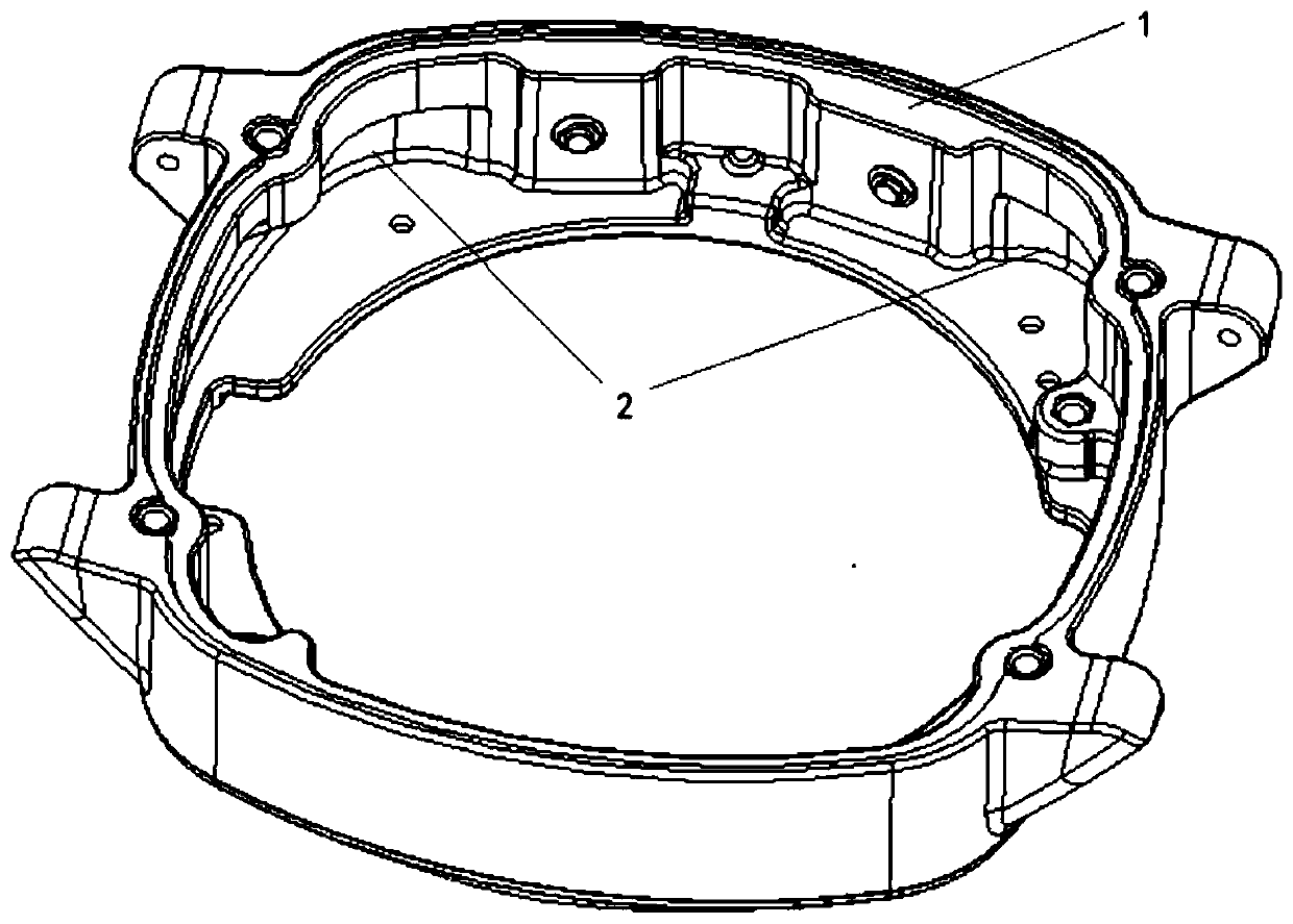
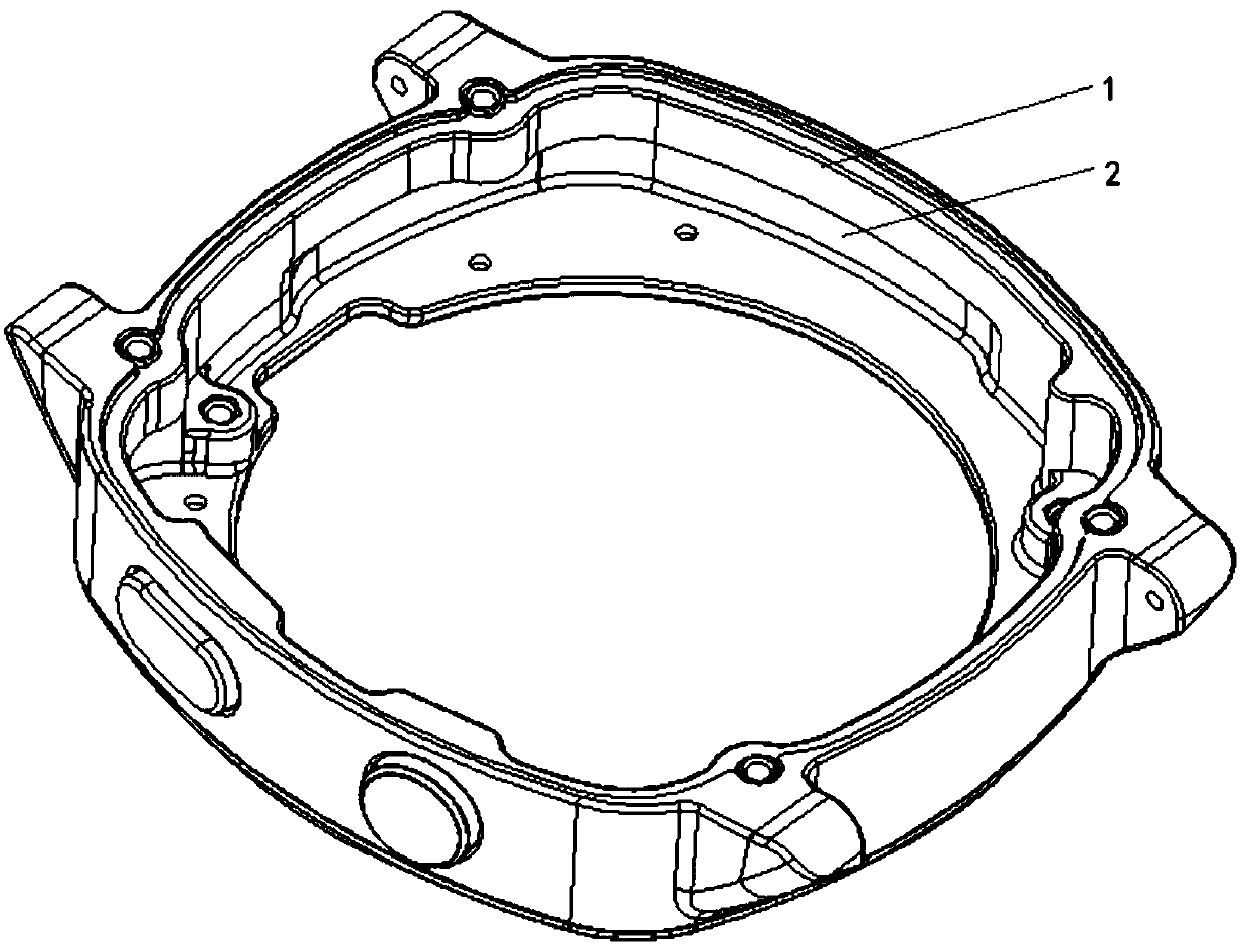
[0019] The first embodiment of the present invention relates to a ceramic smart wearable device, which has a better communication effect than ordinary ceramic smart wearable devices, and the user can obtain a better use experience.
[0020] Ceramic smart wearable devices are smart wearable devices that can be directly worn on the user's body or integrated into clothes, such as ceramic smart watches, ceramic smart bracelets or ceramic smart headphones, etc. figure 1 with figure 2 As shown, the ceramic smart wearable device includes: a ceramic casing 1, a main board arranged in the ceramic casing 1, and at least one antenna assembly. The ceramic casing 1 may be a watch casing, a wristband casing, or an earphone casing. In the manner, the ceramic case 1 is a watch as an example, and there is no specific limitation. The antenna assembly is used to communicate with the outside world, and at the same time, the antenna assembly is electrically connected to the main board for transmitting signals to the main board. Among them, the antenna assembly is separated from the outside by the ceramic housing 1, and signal transmission needs to pass through the ceramic housing 1. The ceramic has a relatively large dielectric constant, which has a relatively strong signal blocking capability and a poor transmission capability.
[0021] In this embodiment, the inner wall of the ceramic casing 1 is provided with a accommodating groove 2 along the wall thickness direction. At least one antenna assembly is provided in the accommodating groove 2. The wall thickness of the ceramic housing 1 that separates the antenna assembly from the outside is reduced. The signal blocking ability becomes weak, which makes the signal transmission between the antenna assembly and the outside world stronger. When there are multiple antenna components in the accommodating slot 2, the multiple antenna components in the accommodating slot 2 are the same type of antenna components to avoid mutual interference.
[0022] There are multiple accommodating slots 2 and antenna components and the number is equal, and each antenna component corresponds to each accommodating slot 2 one-to-one. Of course, multiple antenna components can also be provided in the accommodating slot 2. In this embodiment, only Taking an antenna assembly provided in each accommodating slot 2 as an example, there is no specific limitation. It can be seen from the above that each antenna component is arranged in the corresponding accommodating slot 2, which increases the clearance area of ​​the antenna component without increasing the volume of the ceramic smart wearable device. At the same time, the antenna component is separated from the outside when communicating with the outside. The thickness of the ceramic housing 1 is thinner, the signal blocking of the ceramic housing 1 is reduced, the antenna assembly of the receiving slot 2 provided on the ceramic housing 1 has a better communication effect with the outside world, and the response speed of the ceramic smart wearable device It is fast and not easy to lose the signal, which improves the user experience.
[0023] Such as figure 1 with image 3 As shown, the antenna assembly includes: a bracket 3 arranged in the accommodating slot 2 and an antenna (not shown in the figure) arranged on the bracket 3, wherein the bracket 3 has a contact, and the contact is electrically connected to the antenna, After the bracket 3 is installed in the accommodating slot 2, the contacts on the bracket 3 are electrically connected to the main board. Among them, the bracket 3 may be a plastic bracket 3, which has a good signal transmission effect.
[0024] Among them, such as image 3 As shown, the bracket 3 includes: an embedding portion 31 for embedding in the accommodating groove 2 and a main body portion 32 connected to the embedding portion 31, wherein the antenna and contacts (not shown in the figure) are both provided on the main body portion 32. It is worth noting that such as figure 1 with image 3 As shown, the accommodating groove 2 does not penetrate the ceramic housing 1 in the thickness direction of the ceramic housing 1, so that when the antenna assembly is installed in the accommodating groove 2, the embedded portion 31 will be embedded in the ceramic housing 1. The shape of 31 is the same as the shape of the space in the corresponding accommodating groove 2. When the embedding portion 31 is installed in the accommodating groove 2, each groove wall of the accommodating groove 2 and the embedding portion 31 provided in the accommodating groove 2 It completely offsets, so that the mounting position of the bracket 3 in the accommodating groove 2 is displaced without mounting errors. The main body 32 is located outside the accommodating groove 2. The contact is arranged on the side of the main body 32 close to the main board. The contact is a conductive end. The main board is provided with an elastic piece on the side opposite to each bracket 3. When the bracket 3 After being installed in the accommodating slot 2, the contact will abut the corresponding elastic piece and be electrically conducted, so as to realize the electrical conduction between the antenna connected to the contact and the motherboard.
[0025] It is worth noting that the antenna can be arranged on the main body 32 of the antenna in a variety of ways. As a preference, in this embodiment, the antenna is directly etched on the main body 32 by laser using the LDS antenna technology. The antenna made by the antenna technology is very stable, high precision and very slim, which can enhance the headroom. Of course, the antenna can also be installed on the bracket 3 in other ways. In this embodiment, only LDS antenna technology is used as an example, and there is no specific limitation. .
[0026] The embedding part 31 and the accommodating groove 2 can be fixed in a variety of ways. In this embodiment, the embedding part 31 and the accommodating groove 2 are connected by glue. The adhesive connection operation is convenient and the connection is stable, the cost is low, and the antenna is avoided. There is a risk that the components will easily fall off in the ceramic housing 1. Of course, the embedding portion 31 and the accommodating groove 2 may also be connected in other ways. In this embodiment, only bonding is taken as an example, and no specific limitation is made.
[0027] At the same time, in this embodiment, there are 3 accommodating slots 2 and 3 antenna components. One is a main antenna and a main antenna bracket, and the other is a diversity antenna and a powder antenna bracket. , A GPS Bluetooth component composed of GPS Bluetooth antenna and GPS Bluetooth bracket. Such as figure 1 with figure 2 As shown, the three accommodating slots 2 are separated from each other and are respectively opened at three corners in the ceramic housing 1, and the main antenna assembly, the diversity antenna assembly and the GPS Bluetooth component are respectively arranged in the corresponding accommodating slots 2.
[0028] The second embodiment of the present invention relates to a ceramic smart wearable device. The second embodiment is roughly the same as the first embodiment, but the main difference is that the embedded portion 31 and the accommodating groove 2 in the first embodiment are bonded by glue, while in the second embodiment of the present invention, The embedding part 31 is detachably connected with the containing groove 2. The detachable connection has the advantages of convenient installation, strong connection force, stability, and easy maintenance, and can prevent the antenna assembly from falling off the ceramic housing 1.
[0029] The embedding portion 31 and the accommodating groove 2 can be connected by a snap connection. A hook is extended on the embedding portion 31, and a card slot is provided on a groove wall in the accommodating groove 2. When the embedding portion 31 is installed in a designated position in the accommodating groove 2, That is, when the groove wall of the embedded accommodating groove 2 completely abuts against the embedded portion 31, the hook on the embedded portion 31 is embedded in the groove of the accommodating groove 2, and the accommodating portion 31 is realized by the hook and the groove. Installation in slot 2.
[0030] The embedding portion 31 and the accommodating groove 2 can also be detachably connected in other ways, such as plug-in connection, etc. In this embodiment, the clamping connection is only taken as an example, and there is no specific limitation.
[0031] Those of ordinary skill in the art can understand that the above-mentioned embodiments are specific examples for realizing the present invention, and in practical applications, various changes can be made to them in form and details without departing from the spirit and spirit of the present invention. range.

PUM

no PUM

Description & Claims & Application Information

We can also present the details of the Description, Claims and Application information to help users get a comprehensive understanding of the technical details of the patent, such as background art, summary of invention, brief description of drawings, description of embodiments, and other original content. On the other hand, users can also determine the specific scope of protection of the technology through the list of claims; as well as understand the changes in the life cycle of the technology with the presentation of the patent timeline. Login to view more.

Similar technology patents

Heating device and radar housing

PendingCN111263473AReduce blockingReduce or even avoid blockingWave based measurement systemsHeater elementsPhysicsElectric heating
Owner:NINGBO SUNNY AUTOMOTIVE OPTECH

Antenna device and smart watch

ActiveCN108832268AAntenna structure is simpleIncrease clearance areaAntenna adaptation in movable bodiesRadiating elements structural formsPatch antennaEngineering
Owner:YULONG COMPUTER TELECOMM SCI (SHENZHEN) CO LTD

Classification and recommendation of technical efficacy words

  • Increase clearance area
  • Reduce blocking

Antenna device and smart watch

ActiveCN108832268AAntenna structure is simpleIncrease clearance areaAntenna adaptation in movable bodiesRadiating elements structural formsPatch antennaEngineering
Owner:YULONG COMPUTER TELECOMM SCI (SHENZHEN) CO LTD

Autonomous filter element

InactiveUS20100237013A1Improving filter life and performanceReduce blockingMembranesVolume/mass flow measurementMembrane configurationEngineering
Owner:MILLIPORE CORP

Angle adjustable vibration discharging device

InactiveCN107380768AReduce cloggingReduce blockingLarge containersPush pullEngineering
Owner:泉州臻美智能科技有限公司

Annular movement sieve

InactiveCN102179364AReduce blockingImprove production and screening efficiencySievingScreeningEngineeringSieve
Owner:张玉伟

LED headlamp

Owner:南宁燎旺车灯股份有限公司
Why Eureka
Try Eureka