
Technology forming method of small and medium-sized unmanned aerial vehicle composite material outer wing

A technology of composite materials and molding methods, which is applied in the direction of mechanical equipment, combustion engines, internal combustion piston engines, etc., can solve the requirements of high performance and light weight that are not suitable for small and medium-sized UAVs, uneven glue content and thickness, and unfavorable environments Protection and other issues to achieve the effect of solving rapid mass production, uniform load distribution, and shortening the production cycle

Active Publication Date: 2019-09-03
XIAN AISHENG TECH GRP +1
View PDF4 Cites 11 Cited by
  • Summary
  • Abstract
  • Description
  • Claims
  • Application Information

AI Technical Summary

Problems solved by technology

This method is a traditional composite material outer wing structure molding method, which mainly realizes the overall weight reduction of the outer wing structure through FRP molding and foam sandwich structure, but this method has problems such as high production cost, long production cycle, and environmental protection. Each part needs to be molded and assembled together, and the manufacturing process needs to be cured and molded three times. The FRP molding operation is not conducive to environmental protection; at the same time, compared with prepreg molding, the product weight, glue content and thickness achieved by this method are larger. Problems such as unevenness are not suitable for the high performance and lightweight requirements of small and medium-sized UAVs

Method used


Image

  • Technology forming method of small and medium-sized unmanned aerial vehicle composite material outer wing
  • Technology forming method of small and medium-sized unmanned aerial vehicle composite material outer wing
  • Technology forming method of small and medium-sized unmanned aerial vehicle composite material outer wing

Examples


Embodiment Construction

[0051] Now in conjunction with embodiment, accompanying drawing, the present invention will be further described:

[0052] The first step, the manufacture of product forming molds:

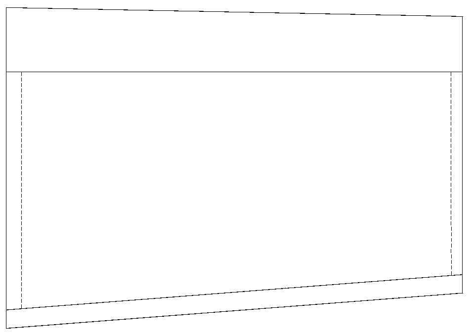
[0053] refer to figure 1 , figure 2 , the outer wing of composite material is mainly composed of the leading edge of the outer wing and the main structure; the left end of the main structure is provided with rib grooves for installing rib connectors, and the right end is provided with a shape depression for installing wingtip fairings.

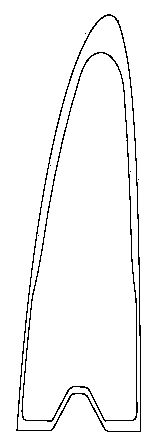
[0054] refer to image 3 The leading edge of the outer wing is a closed composite tubular laminated rigid body with both ends open, which not only effectively ensures the good force and impact resistance of the leading edge, but also facilitates the separation of the leading edge from the main structure. Easy disassembly and replacement when damaged. refer to Figure 4 The bottom surface of the front edge is connected to the main structure by the left positi...


PUM


Abstract

The invention relates to a technology forming method of a small and medium-sized unmanned aerial vehicle composite material outer wing. The method comprises the following steps of forming mold manufacturing, front edge silicon rubber core mold manufacturing, film bag body manufacturing, outer wing front edge manufacturing, and outer wing main body manufacturing; after surface treatment is correspondingly carried out on bonding areas corresponding to the outer wing front edge and a main body front beam surface, and structure double-sided adhesive tapes with the same shape as that of the bondingareas are tore to remove isolation paper on one sides, the adhesive surfaces are adhered to the bonding areas of the outer wing front edge, then solating films on the other sides of the structural adhesive tapes are tore, and the outer wing front edge is horizontally embedded into a boss of the corresponding position of the outer wing main body through a positioning groove at the left end of theouter wing front edge so as to obtain a composite material integral structure outer wing product. According to the technology forming method, the problem of limitation of multiple curing forming, andthe uniformity of the product quality and the thickness are improved.

Description

technical field [0001] The invention belongs to the technical field of UAV composite material forming technology, and relates to a small and medium-sized UAV composite material outer wing technology forming method. Background technique [0002] At present, the outer wings of domestic UAVs are mostly assembled by glued skin, balsa ribs and beams. The skin is usually formed by wet hand-laid FRP, and the balsa ribs and beams are usually aviation laminates or wooden laminated FRP. Structure; as prepreg materials are used more and more widely, the prepreg molding method not only has uniform glue content, light weight, comprehensive mechanical properties and high environmental adaptability, but also is more conducive to the realization of design / manufacturing integration , not only by realizing the overall molding of the outer wing structure, but also taking advantage of the overall molding advantages of composite materials to achieve effective weight reduction, and to enable the ...

Claims


Application Information

Patent Timeline
Patent Type & Authority Applications(China)
IPC IPC(8): B29C70/34B29C70/54B29C33/38B29C33/40
CPCB29C33/3835B29C33/3892B29C33/405B29C70/342B29C70/54Y02T10/40
Inventor 赵伟超童话孙奇
Owner XIAN AISHENG TECH GRP
Learn More