Gear shaft clearance adjustment structure for steering device

A clearance adjustment, gear shaft technology, applied in the direction of mechanical steering gear, belt/chain/gear, components with teeth, etc., can solve the problem that the steering gear cannot be further improved, the impact noise of the gear shaft cannot be improved, etc., to ensure No abnormal noise operation, reduce the risk of wear and tear, avoid the effect of collision and abnormal noise

Active Publication Date: 2019-09-03
CHERY AUTOMOBILE CO LTD
View PDF13 Cites 1 Cited by
  • Summary
  • Abstract
  • Description
  • Claims
  • Application Information

AI Technical Summary

Problems solved by technology

At present, the adjustment structure adopted by the rack-and-pinion steering gear is mainly by adjusting the stiffness of the coil spring 4 at the rack part or adjusting the compression amount of the coil spring 4 to change the parameters such as the pressing force applied to the pressing block 3 to limit the gear. The swing of the rack can solve the problem of the rack and pinion steering gear changing direction and the abnormal sound of the bumpy road, but the adjustment of the spring parameters can only increase the force exerted by the pressure block 3 on the rack 2 in the axial direction, and limit the swing of the rack 2. However, it cannot improve the relative movement of the gear shaft 1 and the rack 2 along the axial direction of the gear and the impact noise caused by the movement of the pressure block 3 in the radial direction after being subjected to the reaction force exerted by the rack 2. The problem of abnormal road noise still cannot be further improved, and the abnormal noise will become more and more obvious after the vehicle has been running for a period of time

Method used


Image

  • Gear shaft clearance adjustment structure for steering device
  • Gear shaft clearance adjustment structure for steering device
  • Gear shaft clearance adjustment structure for steering device

Examples


Embodiment 1

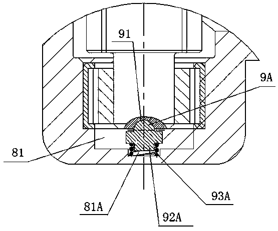
[0021] Such as image 3 As shown, as a preferred embodiment, the top of the support base 9 is provided with a hemispherical convex portion 9A, and the supporting arc surface 91 is the surface of the hemispherical convex portion 9A. Preferably, the elastic structure includes a connecting column 92A and a spring 93A arranged at the bottom of the support seat 9, the end surface of the gear shaft hole 81 is provided with a counterbore 81A for fixing the spring 93A, the upper end of the spring 93A is socketed with the connecting column 92A, and the spring 93A The lower end is fixed in the counterbore 81A. This type of elastic structure can ensure the stability of the movement of the support seat 9 .

Embodiment 2

[0023] Such as Figure 4 As shown, as another preferred embodiment, the top surface of the support seat 9 is provided with a hemispherical groove 91B, and a circular steel ball 92B is arranged in the hemispherical groove 91B, and the supporting arc surface is the shape of the circular steel ball 92B. surface. Preferably, the elastic structure includes a diaphragm spring 93B provided at the bottom of the support seat 9, the end surface of the gear shaft hole 81 is provided with a second counterbore 81B for accommodating the deformation of the diaphragm spring 93B, and the diaphragm spring 93B is overlapped and fixed on the second The opening of counterbore 81B. With this type of elastic structure, the components are easy to assemble, and the possibility of abnormal noise generated by the components of the elastic structure itself can be reduced. Preferably, grease is coated inside the hemispherical groove 91B to increase the rotational flexibility of the round steel ball 92B....


PUM


Abstract

The invention provides a gear shaft clearance adjustment structure for a steering device. Abrasion of internal parts of the steering device can be effectively reduced, axial clearances of gear shaftsare eliminated, and the abnormal sound problem is avoided. The gear shaft clearance adjustment structure comprises a steering device shell, a steering gear shaft and a rack which are engaged with eachother are arranged in the steering device shell, the steering gear shaft and the rack are arranged in a gear shaft hole and a rack hole correspondingly, the steering gear shaft is connected with thegear shaft hole through a rotating bearing, a clearance adjustment mechanism is arranged between the end face of the steering gear shaft and the end face of the gear shaft hole and comprises a supporting seat, a supporting arc face in sliding fit with the end face of the steering gear shaft is arranged at the top of the supporting seat, and the supporting seat and the gear shaft hole are fixed through an elastic structure.

Description

technical field [0001] The invention relates to the technical field of automobile steering systems, in particular to a gear shaft gap adjustment structure of a steering gear. Background technique [0002] Since the development of the automobile market, people's requirements for the comfort of passenger cars have been increasing day by day, and they are becoming more and more sensitive to the abnormal noise produced when the steering wheel of the vehicle changes direction or when passing a bumpy road. The rack and pinion steering gear with tie rod assembly is an important component of the car. With the long-term driving of the car, the parts of the steering gear will be worn due to relative movement, and the gap between the parts will also change. It becomes larger, so it is easy to produce abnormal noise, and even reduce the performance of the steering system, which affects the performance of the vehicle and also affects the driving comfort of the driver. [0003] At presen...

Claims


Application Information

Patent Timeline
Patent Type & Authority Applications(China)
IPC IPC(8): B62D3/12F16H55/28
CPCB62D3/12F16H55/28
Inventor 裴洪莲陈铭杨猛
Owner CHERY AUTOMOBILE CO LTD
Why Eureka
Try Eureka