
Display panel, display device and attaching method of fingerprint module

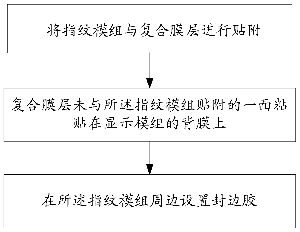
A display panel and fingerprint module technology, applied in identification devices, lamination devices, chemical instruments and methods, etc., can solve problems such as inconsistent Young's modulus, aggravated indentation, and affecting display effects, so as to reduce bonding Stress, eliminate indentation, improve the effect of yield

Active Publication Date: 2019-09-03
BOE TECH GRP CO LTD +1
View PDF5 Cites 11 Cited by
  • Summary
  • Abstract
  • Description
  • Claims
  • Application Information

AI Technical Summary

Problems solved by technology

[0003] For the above attachment methods, since the fingerprint module is directly attached to the back film of the display module, the display module is attached by frame glue and fingerprint module. Attached two times of lamination stress; and because the thermal expansion coefficient and Young's modulus of the frame glue, edge sealant, and display module back film are inconsistent, the indentation after lamination and reliability will increase, making the point screen During the display process, indentations appear in the area of ​​the fingerprint module, which affects the display effect

Method used


Image

  • Display panel, display device and attaching method of fingerprint module
  • Display panel, display device and attaching method of fingerprint module
  • Display panel, display device and attaching method of fingerprint module

Examples


Embodiment Construction

[0016] The application will be further described in detail below in conjunction with the accompanying drawings and embodiments. It should be understood that the specific embodiments described here are only used to explain related inventions, rather than to limit the invention. It should also be noted that, for ease of description, only parts related to the invention are shown in the drawings.

[0017] It should be noted that, in the case of no conflict, the embodiments in the present application and the features in the embodiments can be combined with each other. The present application will be described in detail below with reference to the accompanying drawings and embodiments.

[0018] Please refer to figure 1 , this embodiment provides a display panel, including a display module 1, a heat dissipation film layer 2 is provided on the back film of the display module 1, a first opening 6 is provided on the heat dissipation film layer 2, and the A composite film layer 3 is a...


PUM

PropertyMeasurementUnit
Lengthaaaaaaaaaa

Abstract

The invention discloses a display panel, a display device and an attaching method of a fingerprint module. The display panel comprises a display module; a heat dissipation film layer is arranged on aback film of the display module, a first opening is formed in the heat dissipation film layer, a composite film layer is arranged in the first opening, and the fingerprint module is attached to the composite film layer; the composite film layer comprises a supporting layer and a buffer layer which are bonded with each other, and the supporting layer is close to the fingerprint module. According tothe technical scheme provided by the embodiment of the invention, the composite film layer is arranged as the connecting layer between the fingerprint module and the display module, the composite film layer absorbs impact stress through the buffer layer and fixes and supports the fingerprint module through the supporting layer, and indentations caused by fitting pressure can be eliminated; according to the further provided attaching method, the attaching stress borne by the display module can be effectively reduced, the influence on the display module is avoided, the problem of mold printingduring laminating of the fingerprint module is effectively solved, and the yield of products is increased.

Description

technical field [0001] The invention generally relates to the display field, and in particular to a bonding method of a display panel, a display device and a fingerprint module. Background technique [0002] In the existing under-screen fingerprint recognition technology in the display field, the process of attaching the fingerprint module is generally as follows: the frame glue is attached to the back film of the display module under a certain pressure; secondly, the fingerprint module is attached with a certain pressure. It is attached to the frame glue; finally, the edge sealing glue is dotted around the fingerprint module to fix the fingerprint module. [0003] For the above-mentioned attachment method, since the fingerprint module is directly attached to the back film of the display module, the display module is subjected to two lamination stresses of the frame adhesive attachment and the fingerprint module attachment; and due to the frame adhesive and edge sealant The...

Claims


Application Information

Patent Timeline
IPC IPC(8): G06K9/00G09F9/00
CPCG09F9/00G06V40/13H05K7/20963G06F1/20G06F1/203G06F1/1684G06F1/1637G06F1/1601G06F2200/1612B32B37/12B32B2457/20G06V40/1318
Inventor 杨恕权
Owner BOE TECH GRP CO LTD
Learn More