Shower room floor drainage structure

A technology of drainage structure and floor, applied in drainage structures, floors, waterway systems, etc., can solve problems such as easy overflow of shower room, water can not be discharged in time, and the impact of downstairs users.

Inactive Publication Date: 2019-09-06
泉州昌荣贸易有限公司
View PDF6 Cites 0 Cited by
  • Summary
  • Abstract
  • Description
  • Claims
  • Application Information

AI Technical Summary

Problems solved by technology

[0003] The floor of the existing shower room is usually equipped with a floor drain. The floor drain is connected to the drain port, and the water is drained through the floor drain. However, since there is only one drain port, if the water is used in the shower room for a long time, it is very easy to cause the wat...

Method used


Image

  • Shower room floor drainage structure
  • Shower room floor drainage structure
  • Shower room floor drainage structure

Examples


Embodiment Construction

[0017] The present invention will be further described below in conjunction with the accompanying drawings and specific embodiments.

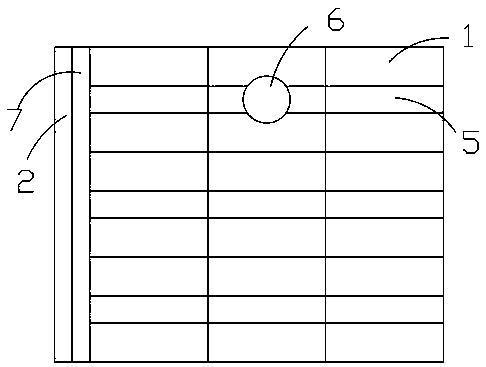
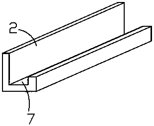
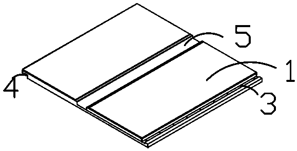
[0018] Such as Figure 1-Figure 3 As shown, the present invention discloses a shower room ground drainage structure, which includes a shower room waterproof floor body formed by splicing several unit boards 1 in sequence, and a water retaining strip 2 arranged outside the waterproof floor body. Each panel 1 includes a first splicing structure arranged on the front of one side, and a second splicing structure arranged on the back of the other side to cooperate with the first splicing structure. The unit panels 1 are all made of SMC. Between the gaps adjacent to the unit board 1, between the unit board 1 and the water retaining strip 2, between the unit board 1 and the wall, and between the water retaining strip 2 and the wall are provided with waterproof Sealing tape, the front of the unit plate 1 is provided with a drainage groove 5, the depth...


PUM


Abstract

The invention discloses a shower room surface drainage structure, which includes a waterproof floor body and a water retaining strip arranged on the outer side of the waterproof floor body. Each unitplate includes a first splicing structure arranged on the front side of one side of the unit plate and a second splicing structure arranged on the back side of the other side of the unit late, the unit plate is made of an SMC, a drainage ditch groove is formed in the front side of the unit plate, the depth of the drainage ditch groove is less than the thickness of the unit plate, drainage ditch grooves of each rank unit plates communicate in turn, drainage ditch grooves of each row unit plates are parallel to one another, a drainage groove is formed in the water retaining strip, the drainage groove communicates with each rank drainage ditch grooves, one of the unit plates is provided with a floor drain mounting hole corresponding to a drainage opening of a shower room, the floor drain mounting hole communicates with the drainage ditch groove on the unit plate, each unit plate is detachably provided with a cover plate for closing the drainage ditch groove correspondingly, and the coverplate is provided with a leakage hole communicating with the drainage ditch groove.

Description

technical field [0001] The invention relates to smart home, in particular to a floor drainage structure for a shower room. Background technique [0002] With the development of people's life, the use of shower rooms has become more and more extensive, gradually replacing the use of the original bathtub, because the shower is more convenient and more hygienic than the bath. [0003] The floor of the existing shower room is usually equipped with a floor drain. The floor drain is connected to the drain port, and the water is drained through the floor drain. However, since there is only one drain port, if the water is used in the shower room for a long time, it is very easy to cause the water to not be discharged in time, and it is very easy to drain. The overflow of the shower room causes water overflow on the ground in the bathroom, and the bathroom is usually only waterproofed on the floor of the shower room when the bathroom is decorated, and other places are only tiled, whi...

Claims


Application Information

Patent Timeline
IPC IPC(8): E04F15/02E04B1/66E03F5/04
CPCE03F5/04E03F5/0408E04B1/66E04F15/02
Inventor 庄少峰杨瑾
Owner 泉州昌荣贸易有限公司
Why Eureka
Try Eureka