Mold fitting device and method for splicing joints of prestressed ribbed superimposed sheets

A laminated slab and prestressed technology, which is applied in the field preparation of formwork/formwork/work frame, building components, construction, etc., can solve the problems of long time for joint mold matching and difficulty in joint joint mold matching, and achieves Convenience for patchwork butt joint, accurate patchwork and avoid misalignment

Active Publication Date: 2019-09-06
CHINA MCC17 GRP
View PDF7 Cites 1 Cited by
  • Summary
  • Abstract
  • Description
  • Claims
  • Application Information

AI Technical Summary

Problems solved by technology

[0003] The purpose of the present invention is to solve the problems of difficult seam matching and long time for seam matching, and propose a joint mold matching device and method for prestressed ribbed laminated slabs

Method used


Image

  • Mold fitting device and method for splicing joints of prestressed ribbed superimposed sheets
  • Mold fitting device and method for splicing joints of prestressed ribbed superimposed sheets
  • Mold fitting device and method for splicing joints of prestressed ribbed superimposed sheets

Examples


Embodiment 1

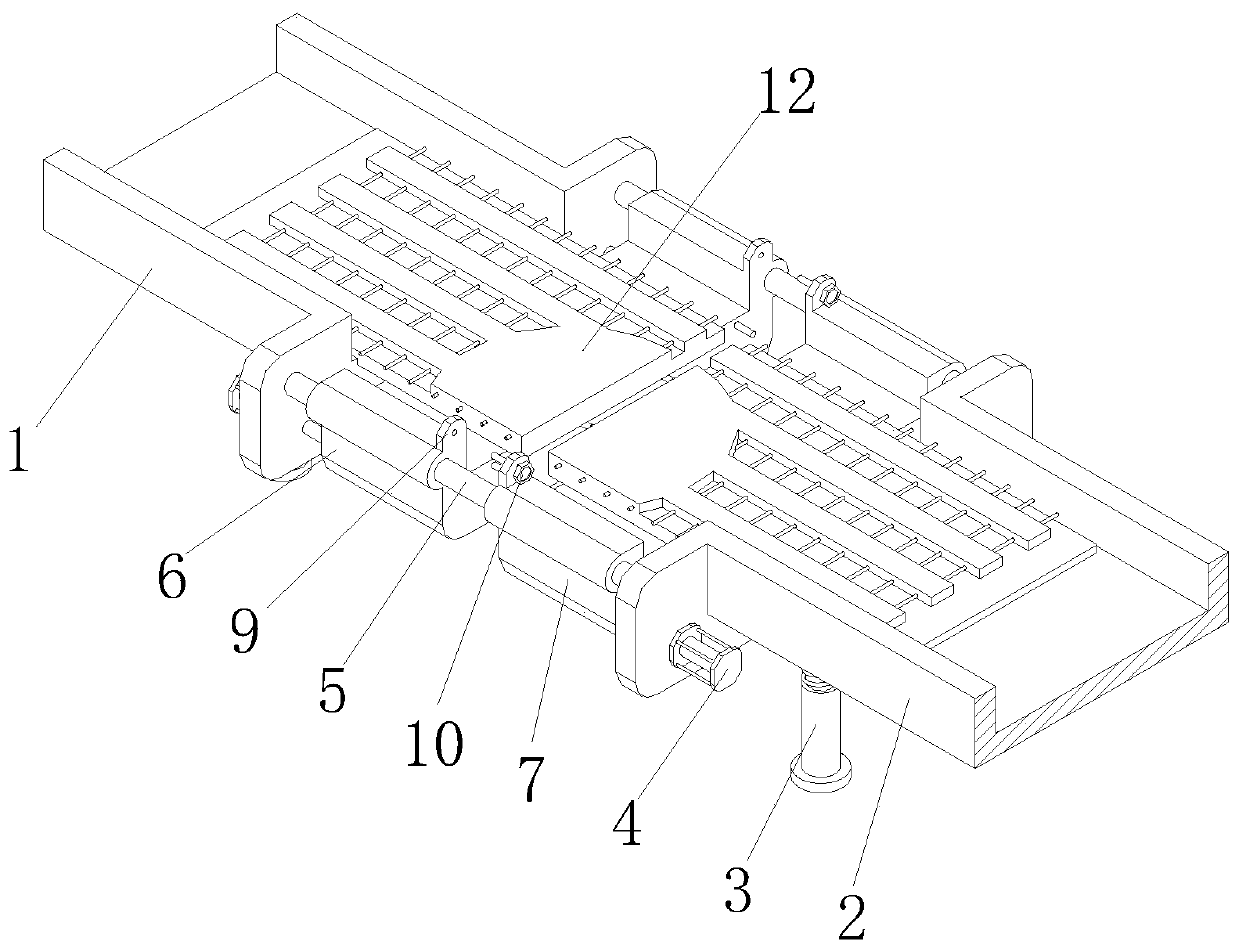
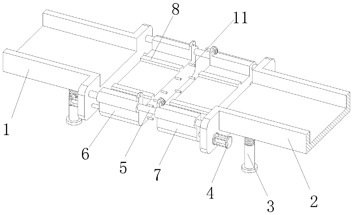
[0026] Embodiment 1: refer to Figure 1-3 As shown, a prestressed ribbed laminated plate seam matching device includes a first shelf 1 and a second shelf 2, and the bottoms of the first shelf 1 and the second shelf 2 are fixedly installed with several supporting bases 3. The bottom of the support base 3 is fixed with anti-skid pads. There are two mutually symmetrical guide rods 5 between the first shelf 1 and the second shelf 2. The two guide rods 5 are respectively located on the first shelf 1. The two ends of the two guide rods 5 are respectively fixedly connected with the corresponding first shelf 1 and the second shelf 2, and the guide rod 5 is provided with a first template 6 at one end of the first shelf 1. A template 6 is clamped on the guide rod 5, and is slidably connected with the guide rod 5, and the guide rod 5 is located at one end of the second shelf plate 2 to be provided with a second template 7, and the second template 7 is clamped on the guide rod 5, and Sli...

Embodiment 2

[0029] Embodiment 2: refer to Figure 1-3 As shown, a prestressed ribbed laminated joint joint mold matching method includes the following steps:

[0030] Step 1: Control the telescopic cylinder 4 so that the first formwork 6 and the second formwork 7 are close to the corresponding first shelf 1 and second shelf 2;

[0031] Step 2: Place the two laminated plates on the first template 6 and the second template 7 respectively, and then control the telescopic cylinder 4 so that the first template 6 and the second template 7 slide toward each other;

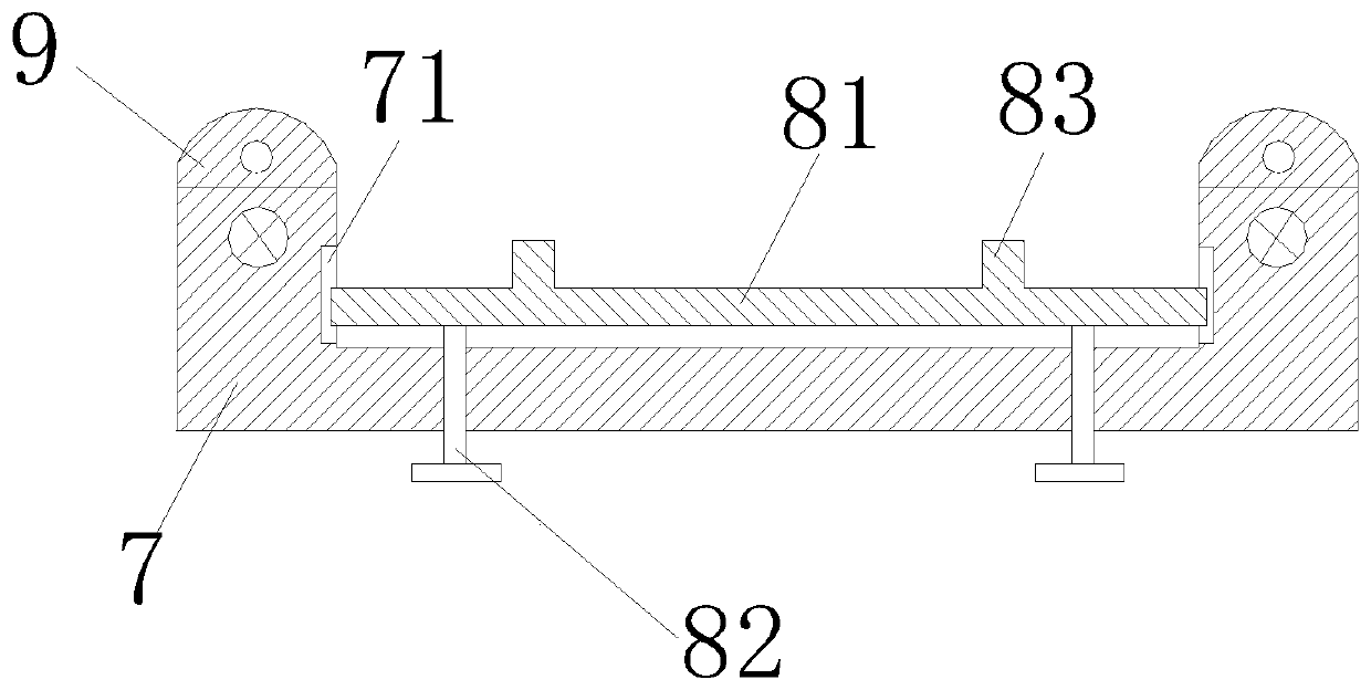
[0032] Step 3: When there is only a gap between the two laminated plates, turn the adjusting bolt 82 to make the sliding plate 81 move slightly up and down until the two laminated plates are on a parallel line;

[0033] Step 4: Continue to control the telescopic cylinder 4 so that the first formwork 6 and the second formwork 7 slide toward each other until the first formwork 6 and the second formwork 7 fit together, and then tighten...


PUM


Abstract

The invention relates to the technical field of building construction, in particular to a mold fitting device for splicing joints of prestressed ribbed superimposed sheets. The mold fitting device includes a first frame plate and a second frame plate, a plurality of supporting bases are fixedly installed at the bottoms of the first frame plate and the second frame plate, two mutually symmetrical guide rods are arranged between the first frame plate and the second frame plate, a first mold plate is arranged at the end, on the first frame plate, of the guide rods, a second mold plate is arrangedat the end, on the second frame plate, of the guide rods, telescopic air cylinders are fixedly and correspondingly installed on both sides of the bottom ends of the first frame plate and the second frame plate, the first mold plate and the second mold plate are provided with butt mechanisms correspondingly, the butt mechanisms are fixedly connected with the first frame plate and the second frameplate correspondingly, and the superimposed sheets are placed at the top ends of the butt mechanisms correspondingly. The mold fitting device has the advantages that mold fitting of the splicing joints of the superimposed sheets is more easy and accurate, thus the working efficiency is greatly improved, and the practical applicability is high.

Description

technical field [0001] The invention relates to the technical field of building construction, in particular to a device and a method for matching joints of prestressed ribbed laminated slabs. Background technique [0002] The currently used floor systems are mainly divided into cast-in-place floors, prefabricated floors and assembled integral floors. The construction of cast-in-place floors requires formwork support and demolition, which leads to large material loss, slow construction progress, and easy cracks. The type floor can be produced industrially, the construction progress is fast, and the material is saved, but the integrity, crack resistance and earthquake resistance are poor, and it can only be used in multi-storey buildings with low seismic requirements. The traditional assembled integral floor has industrial potential. The advantages of modernized production, less formwork support, material saving, and fast construction progress, etc., but cracks are prone to oc...

Claims


Application Information

Patent Timeline
Patent Type & Authority Applications(China)
IPC IPC(8): E04G11/36
CPCE04G11/36
Inventor 吴跃明孙则树
Owner CHINA MCC17 GRP
Why Eureka
Try Eureka