
Gear type rotating driving device

A rotary drive, gear-type technology, applied in the direction of gear transmission, transmission, transmission parts, etc., can solve the problems of difficult manual adjustment of equipment rotation angle, occupying a certain space, unusable space, etc., to achieve high practical value and improve Utilization rate, the effect of good lubrication environment

Inactive Publication Date: 2019-09-06
嘉兴砺安贸易有限公司
View PDF0 Cites 0 Cited by
  • Summary
  • Abstract
  • Description
  • Claims
  • Application Information

AI Technical Summary

Problems solved by technology

[0002] Some large-scale equipment needs to be rotated during processing, so it is necessary to install a slewing device. The traditional slewing device mainly uses a simple combination of gears and motors. The meshing parts and rotating parts are directly exposed to the outside, so it is not easy to lubricate and requires frequent maintenance. Due to the simple structure, an additional reducer needs to be installed, which requires more external space. In order to obtain good bearing stability, this type of slewing device needs to occupy a certain amount of space on its own support surface, leaving a lot of unusable space under the equipment. , and the existing equipment mainly uses a single worm gear drive structure as the power source, the equipment is in a self-locking state, and it is difficult to manually adjust the rotation angle of the equipment

Method used


Image

  • Gear type rotating driving device
  • Gear type rotating driving device
  • Gear type rotating driving device

Examples


Embodiment Construction

[0017] The following will clearly and completely describe the technical solutions in the embodiments of the present invention with reference to the accompanying drawings in the embodiments of the present invention. Obviously, the described embodiments are only some, not all, embodiments of the present invention. Based on the technical solutions in the present invention, all other embodiments obtained by persons of ordinary skill in the art without making creative efforts belong to the protection scope of the present invention.

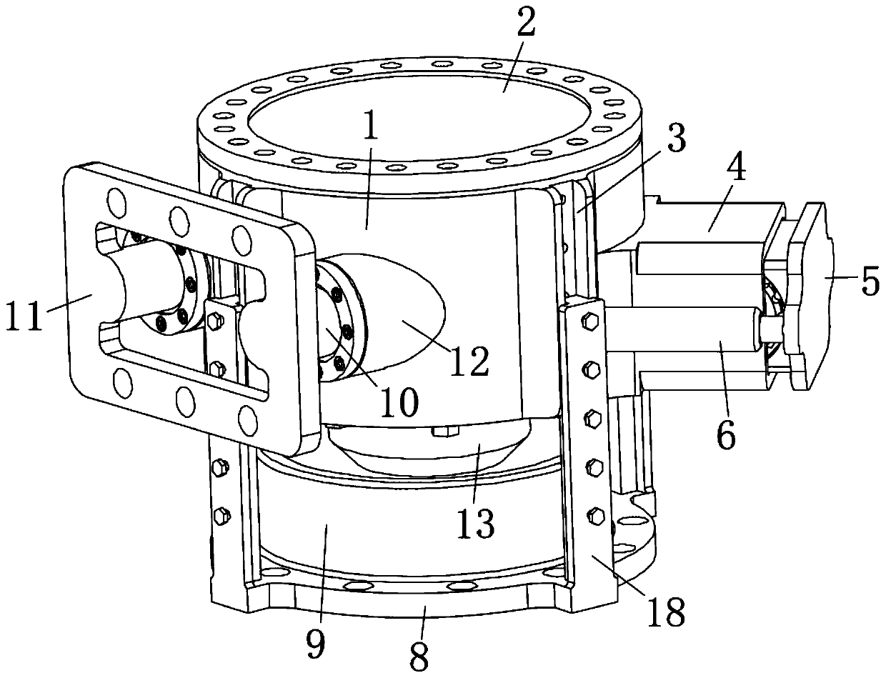
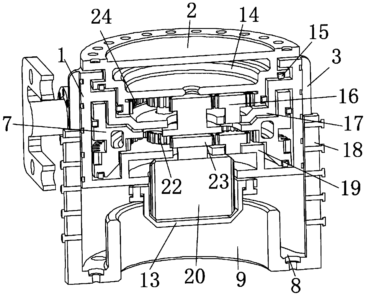
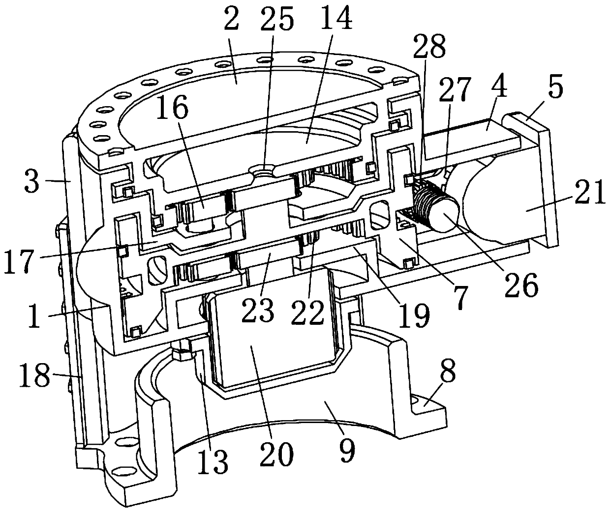
[0018] see Figure 1 to Figure 4 , the present invention provides a technical solution: a gear-type rotary drive device, including an outer shell 1, a lower fixing plate 19 is fixedly installed on the bottom of the outer shell 1, and a main motor 20 is fixedly installed on the lower fixing plate 19, and the outer shell The bottom of 1 is fixed with a protective cover 13 sleeved on the outside of the main motor 20 through bolts, and the output end of th...


PUM


Abstract

The invention relates to the technical field of mechanical equipment design, and discloses a gear type rotating driving device. The gear type rotating driving device comprises an outer shell body, a lower fixing plate is fixedly arranged at the bottom of the outer shell body, moreover, a main motor is fixedly arranged on the lower fixing plate, and a protective cover which sleeves the outer side of the main motor is fixedly arranged at the bottom of the outer shell body through bolts. According to the gear type rotating driving device, switchable dual-power-source drive is adopted, the main motor is used for providing conventional rapid rotating drive, an auxiliary motor finely adjusts a pressure-bearing seat through cooperation between a worm and an outer gear ring and provides a self-locking function, two stages of planetary gear reducers are further designed inside the gear type rotating driving device, so that a reducer is not required to be externally connected, the utilization rate of the internal space is increased, the integration level is higher, moreover, the interior is provided with a better lubricating environment, the running abrasion is effectively reduced, moreover,the structure is easy to detach, and the maintenance is convenient.

Description

technical field [0001] The invention relates to the technical field of mechanical equipment design, in particular to a gear type rotary driving device. Background technique [0002] Some large-scale equipment needs to be rotated during processing, so it is necessary to install a slewing device. The traditional slewing device mainly uses a simple combination of gears and motors. The meshing parts and rotating parts are directly exposed to the outside, so it is not easy to lubricate and requires frequent maintenance. Due to the simple structure, an additional reducer needs to be installed, which requires more external space. In order to obtain good bearing stability, this type of slewing device needs to occupy a certain amount of space on its own support surface, leaving a lot of unusable space under the equipment. , and the existing equipment mainly uses a single worm gear drive structure as the power source, the equipment is in a self-locking state, and it is difficult to ma...

Claims


Application Information

Patent Timeline
Patent Type & Authority Applications(China)
IPC IPC(8): F16H1/30F16H57/04
CPCF16H1/30F16H57/042
Inventor 魏福祥员贤荣房延峰
Owner 嘉兴砺安贸易有限公司
Learn More