
LED backlight with self-cleaning function

A LED backlight and self-cleaning technology, which is applied in the direction of cleaning methods using tools, cleaning methods and utensils, and cleaning methods using gas flow, etc., can solve problems such as affecting functions, inconvenient use, and backlights being contaminated by dust. Guaranteed normal use, convenient use, and good user experience

Pending Publication Date: 2019-09-06
深圳市昊源新辉电子有限公司
View PDF4 Cites 3 Cited by
  • Summary
  • Abstract
  • Description
  • Claims
  • Application Information

AI Technical Summary

Problems solved by technology

[0004] LED backlight is one of the most frequently used backlights. During use, the backlight may be contaminated by dust, which will affect its function.
Chinese patent (authorized announcement number: CN208195124U) discloses a backlight cleaning device, although the device can be used to clean the backlight, but the backlight needs to be placed in the device for cleaning, which is inconvenient to use

Method used


Image

  • LED backlight with self-cleaning function
  • LED backlight with self-cleaning function
  • LED backlight with self-cleaning function

Examples


Embodiment 1

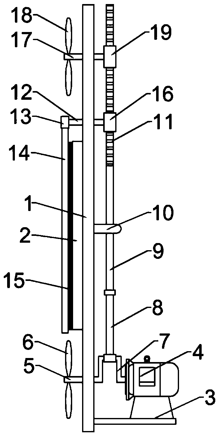
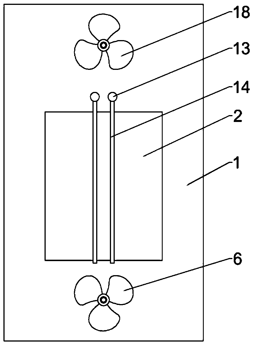
[0022] Example 1: Please refer to Figure 1-4 , a LED backlight with self-cleaning function, comprising a mounting base 1, an LED backlight 2 is fixedly connected to the left side of the mounting base 1, a motor mounting bracket 3 is fixedly connected to the bottom right of the mounting base 1, and the motor mounting bracket 3 is fixedly connected There is a driving motor 4, the output end of the driving motor 4 is fixedly connected to the first rotating shaft 5, and the left end of the first rotating shaft 5 is fixedly connected to the first rotary blade 6;

[0023] When dust is accumulated on the LED backlight 2, the driving motor 4 is turned on, and the driving motor 4 drives the first rotating shaft 5 to rotate, and then drives the first rotary blade 6 to rotate;

[0024] The middle part of the first rotating shaft 5 is fixedly connected with a bell crank 7, and the bell crank 7 is located on the right side of the installation base plate 1. The top of the bell crank 7 is r...

Embodiment 2

[0036] Embodiment 2: The difference between this embodiment and the previous embodiment is that the driven gear 19 meshes with the rear transmission gear 11 . The driven gear 19 can move accordingly no matter whether it is engaged with the front side or the rear side during the meshing process of the transmission teeth 11 .

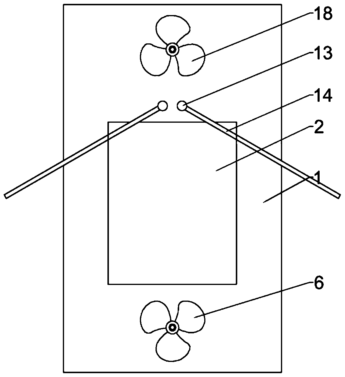
[0037] The working principle of the present invention is: when the dust is accumulated on the LED backlight 2, the drive motor 4 is turned on, the drive motor 4 drives the first rotating shaft 5 to rotate, and then drives the first rotating blade 6 to rotate, and the bell crank 7 rotates while the first rotating shaft 5 rotates. Rotate, and then drive the first transmission rod 8 and the second transmission rod 9 to move, the motion trajectory of the second transmission rod 9 is reciprocating up and down, and then drive the transmission gear 11 to move up and down, and drive the opened swing cleaning when the transmission gear 11 moves upwards The rods 14...


PUM


Abstract

The invention discloses LED backlight with a self-cleaning function, and relates to the LED backlight. The LED backlight includes a mounting bottom plate, the LED backlight is fixedly connected to theleft side of mounting bottom plate, a motor mounting bracket is fixedly connected to the bottom right of mounting bottom plate, the motor mounting bracket is fixedly connected with a driving motor, the output end of the driving motor is fixedly connected with a first rotating shaft, the left end of the first rotating shaft is fixedly connected with a first rotating blade, the middle of the firstrotating shaft is fixedly connected with a crank throw, and the crank throw is located on the right side of the mounting bottom plate. The LED backlight is simple in structure and convenient to use and driven by the motor during using, vertical reciprocating motion of a second transmission rod is realized, the second transmission rod can drive a positioning cleaning shaft to swing, thus bristles are driven to swing to self-clean the LED backlight, normal use of the LED backlight is ensured, the LED backlight can further drive the first rotating blade and a second rotating blade simultaneouslyto blow away floating dust, re-adhering to the LED backlight is avoided, and at the same time the LED backlight can be cooled.

Description

technical field [0001] The invention relates to an LED backlight source, in particular to an LED backlight source with self-cleaning function. Background technique [0002] The backlight is a light source located behind the liquid crystal display, and its luminous effect will directly affect the visual effect of the liquid crystal display module. The LCD itself does not emit light, it displays graphics or the result of its modulation of light. [0003] The backlight is mainly composed of a light source, a light guide plate, optical modules, and structural parts: light source: mainly EL, CCFL and LED backlight types; light guide plate: divided into printing, chemical etching, precision mechanical characterization, light micro film, internal diffusion, hot pressing; optical modules: enhancement film / sheet, diffusion film / sheet, reflector, black / white glue; structural parts: structural parts include: backplane (iron backplane, aluminum backplane, Plastic backboard), plastic f...

Claims


Application Information

Patent Timeline
Patent Type & Authority Applications(China)
IPC IPC(8): G02F1/13357B08B1/00B08B5/02
CPCG02F1/1336B08B1/00B08B5/02
Inventor 唐丽娜黄美容
Owner 深圳市昊源新辉电子有限公司
Learn More