Supercharge Your Innovation With Domain-Expert AI Agents!

Safety type hydraulic electromagnetic circuit breaker and breaking method

A circuit breaker and safety-type technology, which is applied in the field of circuit breaker manufacturing, can solve the problems of long separation time, etc., and achieve the effects of improving safety and reliability, reducing breaking time, and improving breaking capacity

Pending Publication Date: 2019-09-06
浙江百事宝电器股份有限公司
View PDF0 Cites 0 Cited by
  • Summary
  • Abstract
  • Description
  • Claims
  • Application Information

AI Technical Summary

Problems solved by technology

[0003] The object of the present invention is to solve the above problems, provide a reasonable design, and solve the problem of the time required to separate the moving contacts and static contacts in the existing electromagnetic circuit breaker when there is a short-circuit current flowing through it. Long question safety type hydraulic electromagnetic circuit breaker

Method used


Image

  • Safety type hydraulic electromagnetic circuit breaker and breaking method
  • Safety type hydraulic electromagnetic circuit breaker and breaking method
  • Safety type hydraulic electromagnetic circuit breaker and breaking method

Examples


Embodiment 1

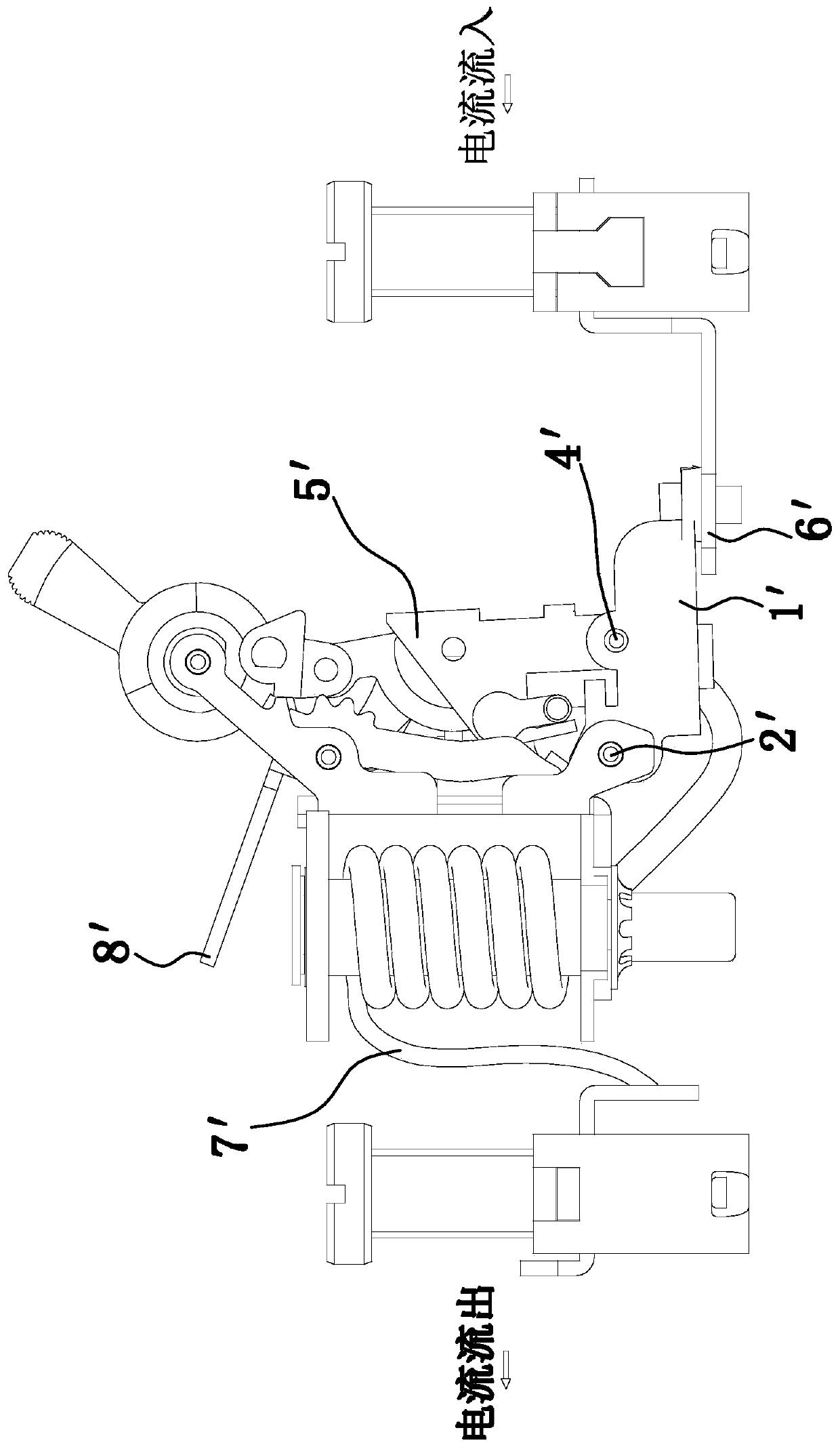
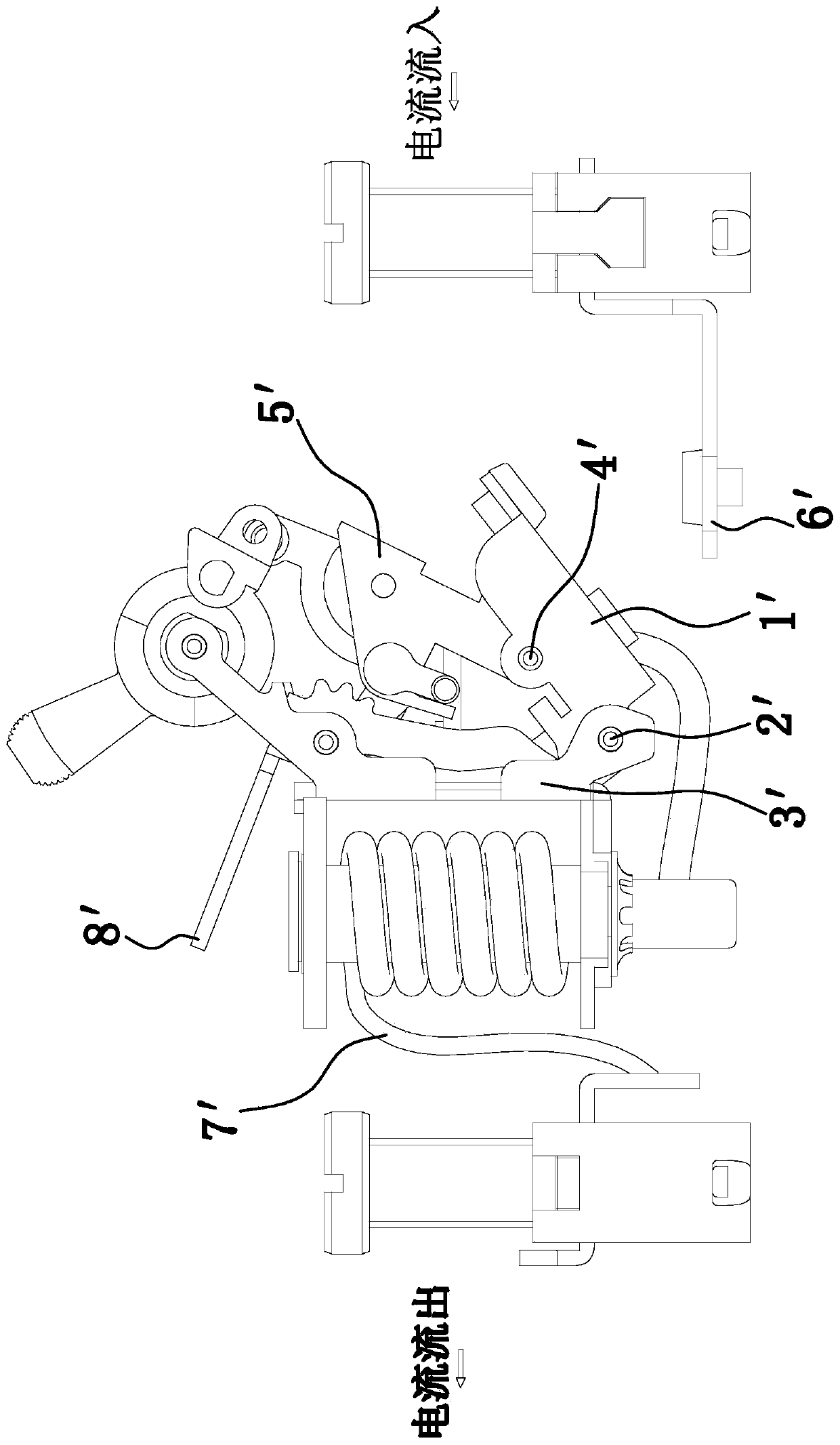
[0036]The safety type hydraulic electromagnetic circuit breaker includes a housing 1, on which is provided an incoming line terminal 2 and an outgoing line terminal 3, and an electromagnetic transmission mechanism 4 is provided between the incoming line terminal 2 and the outgoing line terminal 3, and the electromagnetic transmission mechanism 4 includes The induction coil 402 wound on the delay tube 401, the delay tube 401 is set on the installation frame 403, and also includes a tripping mechanism 404, an armature 405 and a hand brake 406, and the installation frame 403 respectively passes through the fourth hinge 407, the second The five hinges 408 are hinged with the armature 405 and the hand brake 406, the tripping mechanism 404 is hinged with the hand brake 406 through the third hinge 409, the tripping mechanism 404 is also hinged with the moving contact 411 through the first hinge 410, and the moving contact 411 is provided with a movable contact 412, and the static cont...

Embodiment 2

[0044] This embodiment is basically the same as Embodiment 1, except that the electromagnetic transmission mechanism 4 also includes an elastic clamping seat 419 arranged on the housing 1. When the switch is closed, the elastic clamping seat 419 and the Pushed by the electric repulsive force, the movable contact 411 that rotates around the first hinge 410 away from the fixed contact 413 is snap-fitted, so as to prevent the rotating movable contact 411 from rotating. Because if the moving contact 411 rotates away from the static contact 413 by the electric repulsion force, and the induction coil 402 has not attracted the armature 405, the armature 405 will not drive the release mechanism 404 to unlock. Small, the movable contact 411 may turn around, causing the movable contact 412 on the movable contact 411 and the static contact 414 on the static contact 413 to combine again, which may cause danger, and after the elastic clamping seat 419 is set Therefore, only after the tripp...


PUM


Abstract

The invention provides a safety type hydraulic electromagnetic circuit breaker and a breaking method and belongs to the technical field of circuit breaker manufacturing. The problem that the existingbreaking speed is low is solved. The safety type hydraulic electromagnetic circuit breaker comprise a shell, a wire inlet terminal and a wire outlet terminal are arranged on the shell, an electromagnetic transmission mechanism is arranged between the wire inlet terminal and the wire outlet terminal, the electromagnetic transmission mechanism comprises an induction coil wound on a time delay tube,the time delay tube is arranged on an installation frame, the electromagnetic transmission mechanism further comprises a tripping mechanism, an armature and a hand brake; and the installation frame isrespectively hinged with the armature and the like through a fourth hinge piece and a fifth hinge piece, respectively. The safety type hydraulic electromagnetic circuit breaker and the breaking method have the advantages that the breaking time in the breaking process is reduced, so that the breaking capacity of the product can be improved; in addition, an anti-rebound structural design is achieved, it can be ensured that the problem of secondary electrification cannot occur in the breaking process of the circuit breaker, and the safety and the reliability of the breaker can be improved whilethe breaking capacity is improved.

Description

technical field [0001] The invention belongs to the technical field of circuit breaker manufacture, and in particular relates to a safe hydraulic electromagnetic circuit breaker and a breaking method. Background technique [0002] like figure 1 and 2 As mentioned above, the working principle of the existing hydraulic electromagnetic circuit breaker: because the existing movable contact 1' is directly hinged with the installation frame 3' through the hinge shaft 2', and then connected with the tripping mechanism 5 through the hinge shaft 2 4' 'Hinged, such a structural setting makes it impossible for the movable contact 1' to rotate around the hinge axis 2 4', so that even if the movable contact 1' and the static contact 6' are mutually repulsive due to the opposite direction of current When the electric repulsion occurs, the moving contact 1' will not rotate, and the direction of the current flowing through the moving contact 1' and the static contact 6' here is the same, ...

Claims


Application Information

Patent Timeline
IPC IPC(8): H01H73/40H01H73/04H01H73/18
CPCH01H73/40H01H73/04H01H73/18
Inventor 施宏伟孙良权刘福黄杰
Owner 浙江百事宝电器股份有限公司
Features
  • R&D
  • Intellectual Property
  • Life Sciences
  • Materials
  • Tech Scout
  • Unparalleled Data Quality
  • Higher Quality Content
  • 60% Fewer Hallucinations
Learn More