Differential connector and installation structure of bent contact

A technology for differential connectors and installation structures, which is applied in the direction of contact parts, parts of connection devices, fixed/insulated contact members, etc. It can solve the problems of difficult assembly of curved contacts, achieve simple form, ensure stability, and cooperate The effect of stable relationships

Active Publication Date: 2019-09-06
CHINA AVIATION OPTICAL-ELECTRICAL TECH CO LTD
View PDF11 Cites 0 Cited by
  • Summary
  • Abstract
  • Description
  • Claims
  • Application Information

AI Technical Summary

Problems solved by technology

[0004] The purpose of the present invention is to provide a mounting structure of the curved contact, which can solve the problem of difficult assembly of the curved contact in the prior art, thereby improving the efficiency of assembly; another purpose of the present invention is to provide a Structured Differential Connectors

Method used


Image

  • Differential connector and installation structure of bent contact
  • Differential connector and installation structure of bent contact
  • Differential connector and installation structure of bent contact

Examples


Embodiment Construction

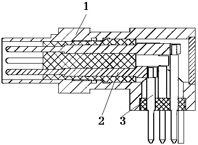
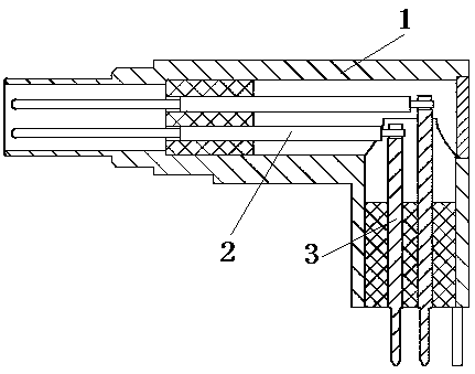
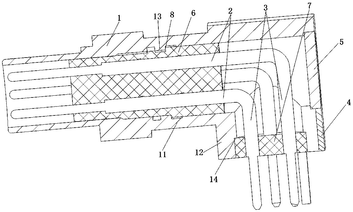
[0050] like Figure 3 to Figure 4 As shown, it is Embodiment 1 of the differential connector in the present invention: the differential connector includes two parts, respectively an outer conductor 1 and a center conductor arranged in the outer conductor 1, and the center conductor is L-shaped, respectively including a horizontal direction. The horizontal section conductor 2 and the vertical section conductor 3 arranged in the vertical direction and perpendicular to the horizontal section conductor 2, and the horizontal section conductor 2 and the vertical section conductor 3 are integrally constructed, and have been assembled before the outer conductor 1 is assembled. Fixed connection.

[0051] In order to ensure that the integrated L-shaped center conductor can be smoothly assembled into the outer conductor 1, the outer conductor 1 is provided with an escape port 4 for inserting the horizontal conductor 2 in the center conductor into the outer conductor 1. The horizontal se...


PUM


Abstract

The invention relates to the technical field of electrical connectors, in particular to a differential connector and an installation structure of a bent contact. The differential connector comprises an outer conductor and a center conductor arranged in the outer conductor. The center conductor is the bent contact. The center conductor comprises a horizontal section conductor and a vertical sectionconductor. A horizontal mounting cavity corresponding to the horizontal section conductor and a vertical mounting cavity corresponding to the vertical section conductor are arranged in the outer conductor. The horizontal section conductor and the vertical section conductor are integrated. The side of the outer wall of the vertical mounting cavity away from the horizontal mounting cavity is provided with an escape port which is used for avoiding the horizontal section conductor and the vertical section conductor so that the center conductor is enabled to enter the outer conductor along the axial direction of the horizontal mounting cavity or the side of the outer wall of the horizontal mounting cavity away from the vertical mounting cavity is provided with an escape port which is used foravoiding the horizontal section conductor and the vertical section conductor so that the center conductor is enabled to enter the outer conductor along the axial direction of the vertical mounting cavity.

Description

technical field [0001] The invention relates to the technical field of electrical connectors, in particular to a differential connector and an installation structure of a bent contact piece. Background technique [0002] Contacts are often used to transmit signals, such as bent contacts used to transmit differential signals, such as Figure 1 to Figure 2 As shown, the differential connector includes an outer conductor 1 and a center conductor arranged in the outer conductor 1. The center conductor is a bent contact piece formed by vertical welding of conductors arranged in the transverse and longitudinal directions, including horizontal conductors 2 and vertical conductors respectively. The segment conductor 3, while the outer conductor 1 includes a horizontal mounting cavity for accommodating the horizontal segment conductor 2 and a vertical mounting cavity for accommodating the vertical segment conductor 3, respectively. figure 1 and figure 2 The difference is that the ...

Claims


Application Information

Patent Timeline
IPC IPC(8): H01R13/40H01R13/02H01R13/516
CPCH01R13/02H01R13/40H01R13/516
Inventor 苏雯
Owner CHINA AVIATION OPTICAL-ELECTRICAL TECH CO LTD
Why Eureka
Try Eureka