Cable laying device

A cable laying and cable technology, which is applied in the field of cable laying devices, can solve the problems of low working efficiency of laying cables, and achieve the effects of stable laying, improving friction and improving working efficiency.

Pending Publication Date: 2019-09-06
HEBEI POWER TRANSMISSION & TRANSFORMATION +2
View PDF0 Cites 4 Cited by
  • Summary
  • Abstract
  • Description
  • Claims
  • Application Information

AI Technical Summary

Problems solved by technology

[0003] The purpose of the present invention is to provide a cable laying device to solve the technical problem of low work efficiency of cable laying in the prior art

Method used


Image

  • Cable laying device
  • Cable laying device
  • Cable laying device

Examples


specific Embodiment approach

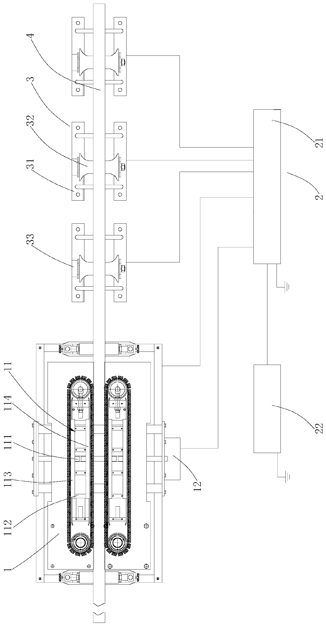
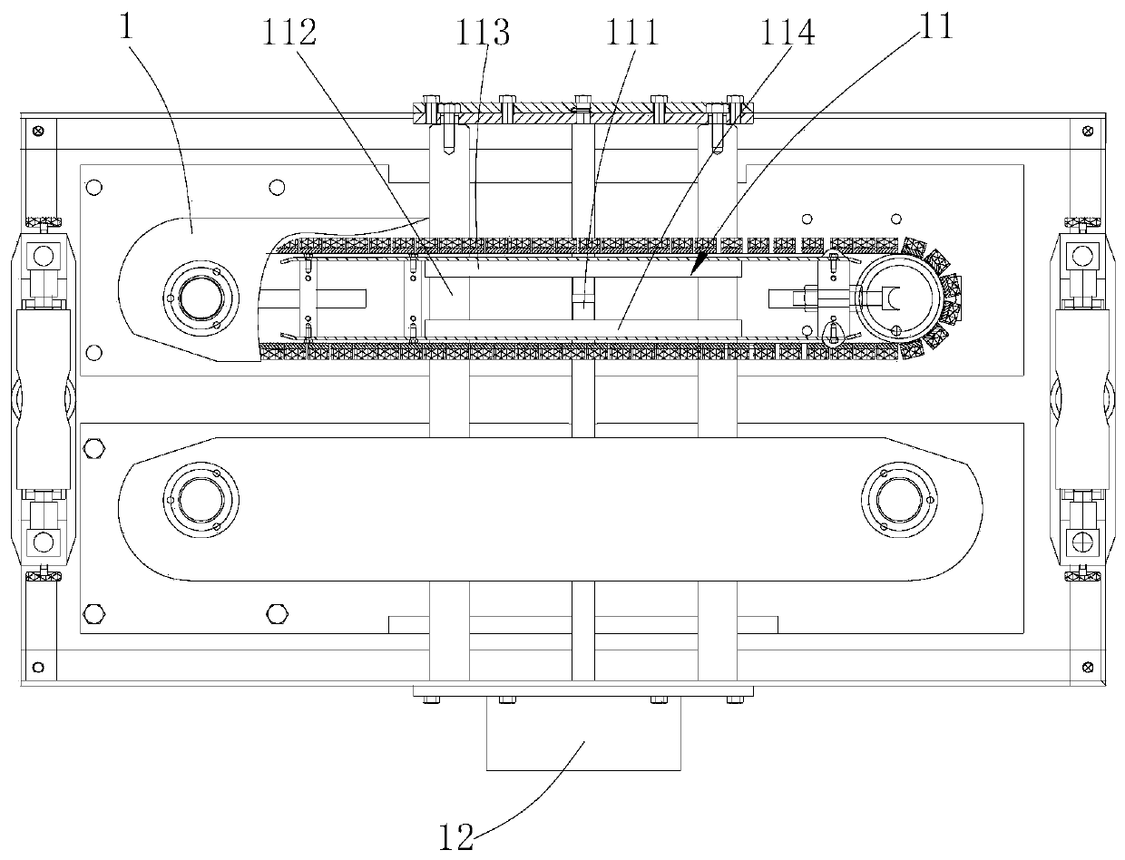
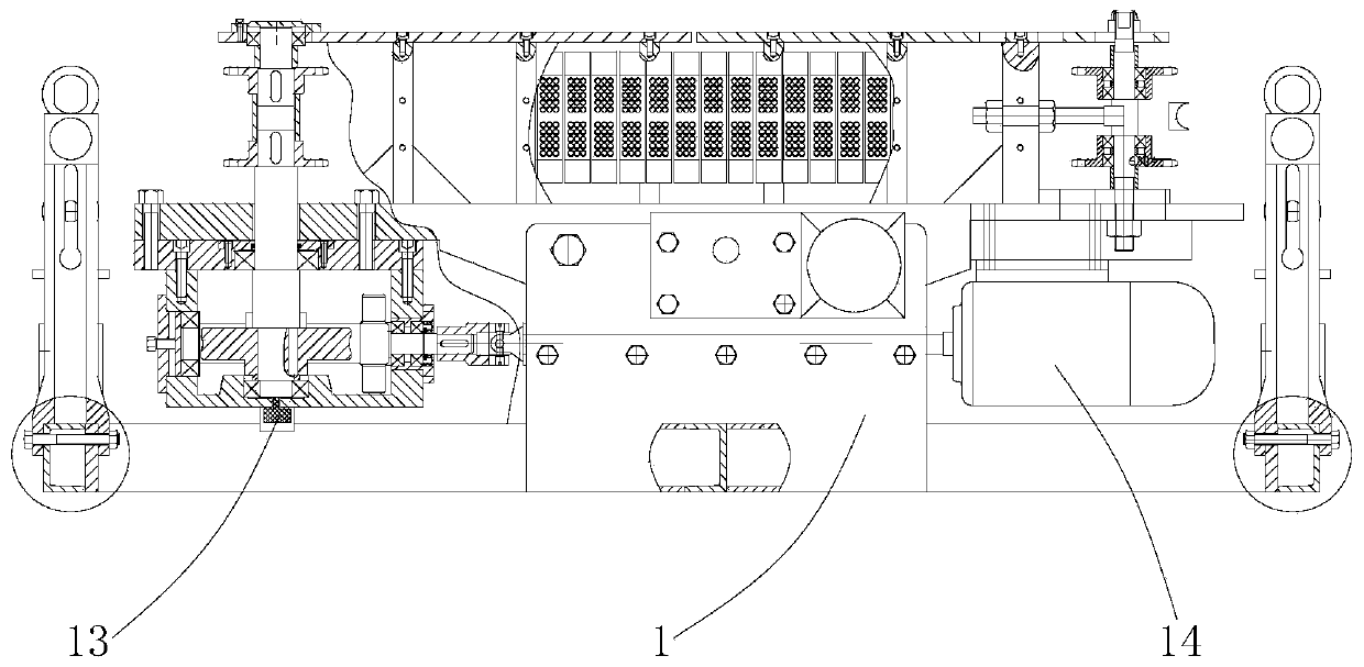
[0052] see figure 1 , Figure 4 and Figure 5 , as a specific embodiment of the cable laying device provided by the present invention, the high-voltage input and output cabinet 21 includes a cabinet body 211, a controller 212 and a power supply 213, and the cabinet body 211 is arranged on one side of the conveyor 1; the controller 212 is arranged on The cabinet 211 is electrically connected to the conveyor 1; the power supply 213 is located in the cabinet 211 and electrically connected to the controller 212, and the controller 212 and the power supply 213 are placed in the cabinet 211 to isolate them from the outside world; When in use, connect the power supply 213 and the controller 212 to the conveyor 1 and the torque motor respectively, and the controller 212 controls the startup, operation and shutdown of the conveyor 1 so that the cable laying device can work normally. When the distance between the two conveyors 113 and 114 is reduced, the controller 212 can control the...


PUM


Abstract

The invention provides a cable laying device and belongs to the technical field of an electric power tool. The cable laying device comprises conveyors, tensioning mechanisms and a control system. Thetensioning mechanisms are arranged in the conveyors; a power assembly is arranged at one side of the conveyors; and the control system is arranged at one side of the conveyors. During use of the cablelaying device, a coiled cable is placed at one side of the two conveyors, then, one end of the cable is arranged at one ends of the two conveyors, and the control system controls the conveyors to work; the cable is laid with the help of friction force introduced by the two conveyors; and meanwhile, the tensioning mechanisms are started to enable the tensioning mechanisms in the conveyors to reduce the gap between the two conveyors so as to improve friction force between the conveyors and the cable, so that the conveyors can maintain a large transmission force to drive the cable to be laid. Through such mode, working efficiency of the cable laying device is improved, and the cable laying device can lay the cable stably.

Description

technical field [0001] The invention belongs to the technical field of electric tools, and more specifically relates to a cable laying device. Background technique [0002] At present, the cable laying construction in the power industry generally transports the coiled cables to the vicinity of the construction site, then manually opens the coiled cables, and then manually clamps the cables to the traditional cable conveyor, because the weight of large cross-section cables is relatively heavy. Large, the cable conveyor is laborious to transport the cable, and the transmission efficiency of the cable conveyor is low due to the reduced friction between the cable conveyor and the cable. Contents of the invention [0003] The object of the present invention is to provide a cable laying device to solve the technical problem of low work efficiency of cable laying in the prior art. [0004] In order to achieve the above object, the technical solution adopted by the present invent...

Claims


Application Information

Patent Timeline
Patent Type & Authority Applications(China)
IPC IPC(8): H02G1/06
CPCH02G1/06
Inventor 刘红利范炜龙封志强路鹏程王中泽唐建涛高进美
Owner HEBEI POWER TRANSMISSION & TRANSFORMATION
Why Eureka
Try Eureka