Pipeline laying device for building construction

A technology for building construction and laying equipment, applied in pipeline laying and maintenance, auxiliary equipment, metal processing equipment, etc., can solve the problems of slow process, large volume, affecting the efficiency of pipeline laying, etc., to improve the process of pipeline welding, The effect of improving efficiency

Active Publication Date: 2020-06-23
聊城九洲建设集团有限公司
View PDF24 Cites 2 Cited by
  • Summary
  • Abstract
  • Description
  • Claims
  • Application Information

AI Technical Summary

Problems solved by technology

The auxiliary equipment suitable for the welding of tap water pipes in the above-mentioned patents has the following disadvantages: during the welding process of the equipment, due to the large volume installed, the whole equipment is relatively long, compared with the traditional welding...

Method used


Image

  • Pipeline laying device for building construction
  • Pipeline laying device for building construction
  • Pipeline laying device for building construction

Examples


Embodiment 1

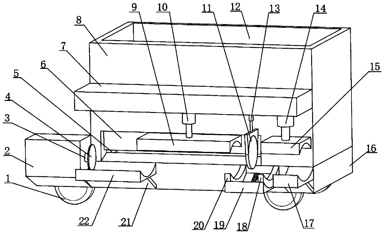
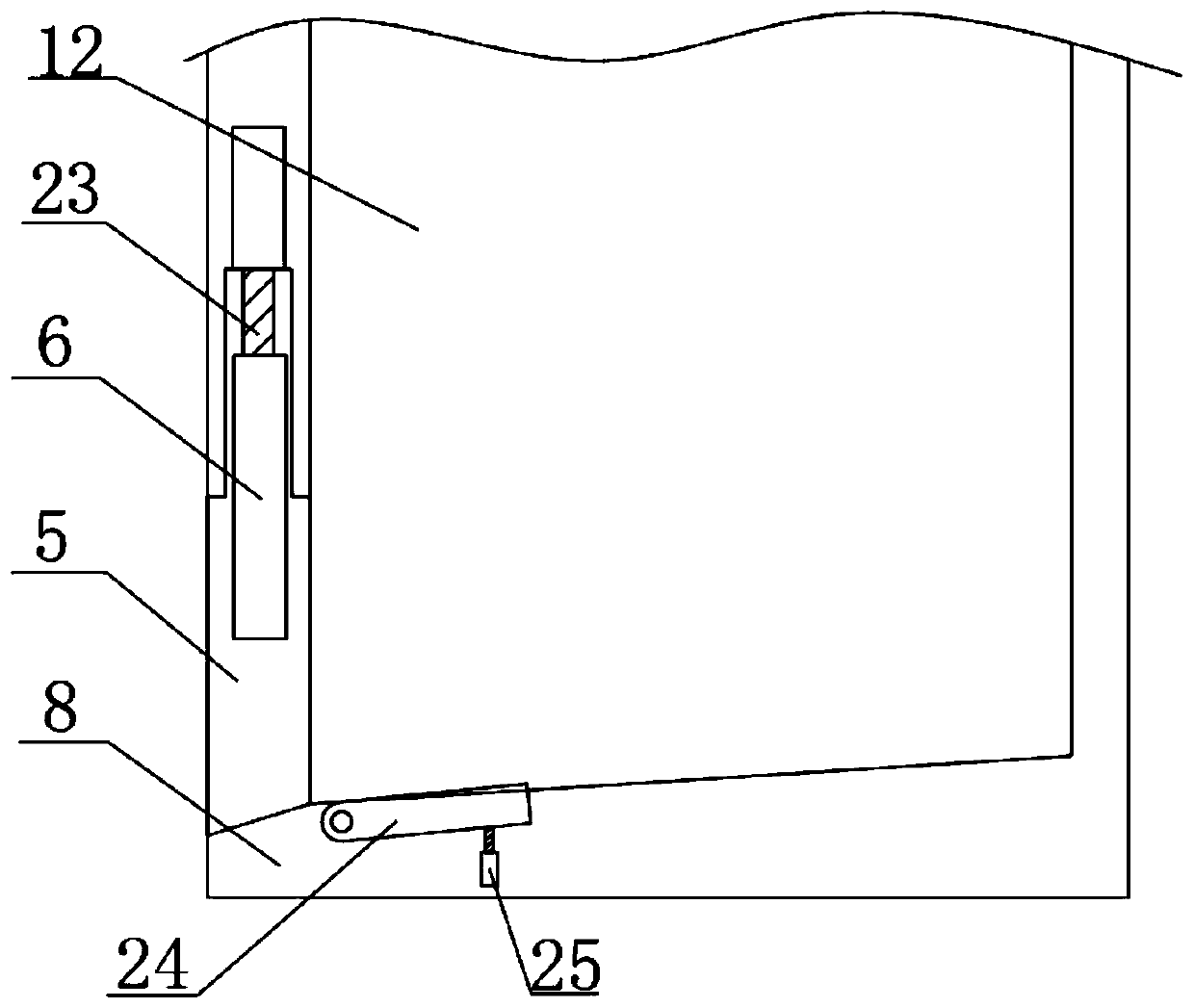
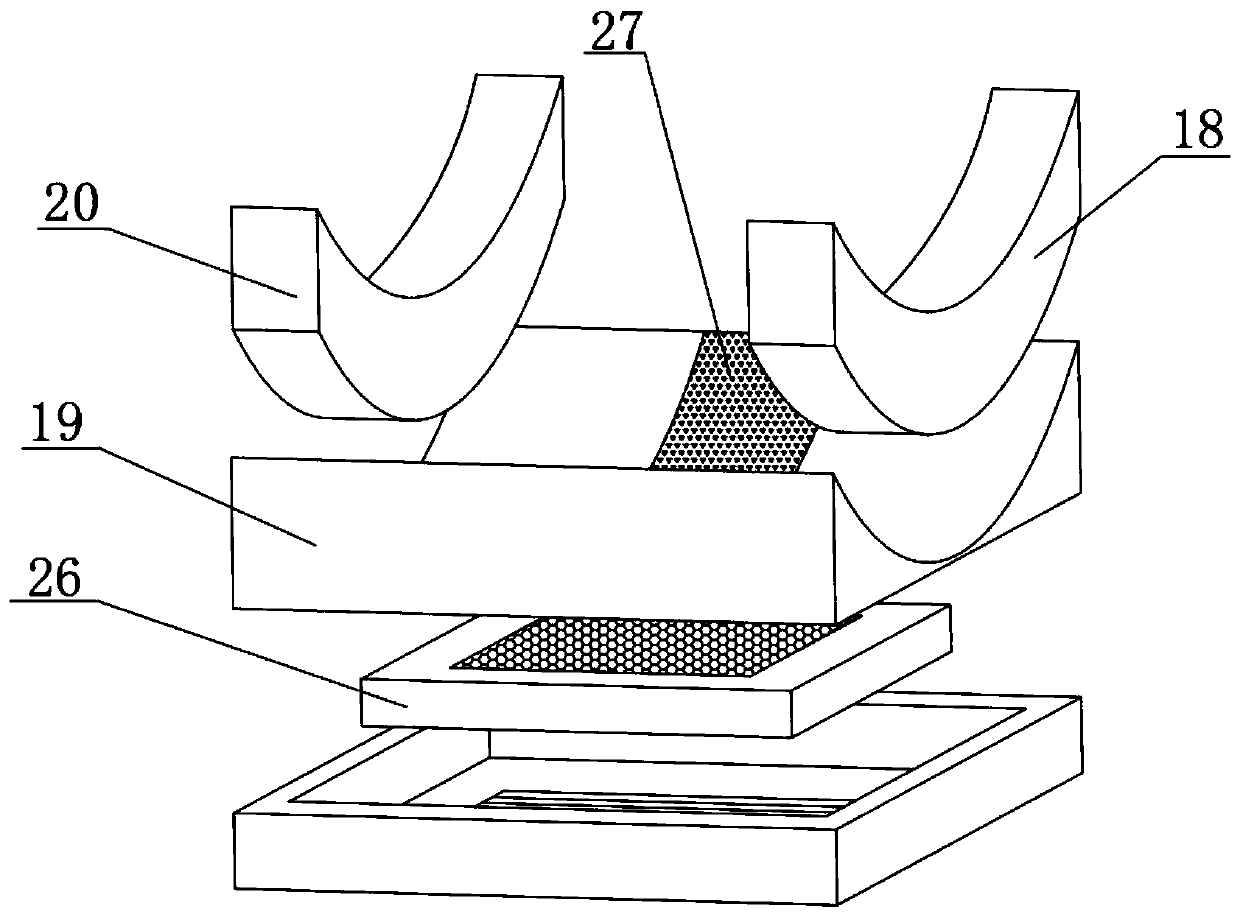
[0029] A pipe laying device for building construction, such as Figure 1-3 As shown, it includes a fixed machine platform 16, the top of the fixed machine platform 16 is connected with a horizontally arranged pipeline cabinet 8 by bolts, the middle of one side of the pipeline cabinet 8 is connected with a horizontally arranged power cabinet 7 by bolts, and one side of the fixed machine platform 16 One end of the platform is connected with a horizontally arranged pallet 1 22 by bolts, and the other end of the fixed machine 16 side is connected with a horizontally arranged pallet 2 17 by bolts, and the tops of the pallet 2 17 and the pallet 1 22 are provided with An arc-shaped groove, one side of the fixed machine platform 16 is located at one end of the supporting platform 2 17 and is connected with a horizontally arranged welding platform 19 by bolts, and one end of the top of the welding platform 19 is connected with a vertically arranged supporting bracket 1 20 by bolts, The...

Embodiment 2

[0033] A pipe laying device for building construction, such as Figure 1-4 As shown, the top of the pallet two 17 and the bottom of the fixed top plate two 15 are all pressed together with a vertically arranged rubber anti-skid bump 28 .

[0034] When the present embodiment is in use, in the second embodiment, the rubber anti-skid bumps installed vertically on the top of the platform two 17 and the bottom of the fixed top plate two 15 can effectively prevent the The welded pipes are unstable, resulting in welding failure, making the welding safer and more reliable.


PUM


Abstract

The invention belongs to the technical field of tap water pipeline laying, and particularly relates to a pipeline laying device for building construction. The pipeline laying device for building construction aims at solving the problem that an existing water pipe welding laying device needs to be placed and then moved for welding, and the pipeline laying efficiency is affected. According to the scheme, the pipeline laying device comprises a fixed machine table, the top of the fixed machine table is connected with a horizontally-arranged pipeline machine box through bolts, the middle of one side of the pipeline machine box is connected with a horizontally-arranged power machine box through bolts, and one end of one side of the fixed machine table is connected with a horizontally-arranged first supporting table through bolts. According to the pipeline laying device for building construction, pipelines can be stored through the pipeline machine box at the top, compared with a traditionalpipeline network, the pipeline laying device has the advantages that the pipelines are stored through welding, and welding and laying actions can be directly carried out through the power machine box;and compared with a traditional mode that the pipelines are firstly transported to the position and then sequentially carried, moved and welded, the pipeline laying device is more convenient and faster, and the tap water pipeline laying efficiency is improved.

Description

technical field [0001] The invention relates to the technical field of tap water pipeline laying, in particular to a pipeline laying device for building construction. Background technique [0002] The pipeline is the pipeline used to send water to the user. The tap water pipeline is responsible for transporting the water flow. The composition of the tap water pipeline needs to be welded together by multiple water pipes in sequence. The tap water pipe adopts the welding method of on-site welding. [0003] After retrieval, the Chinese patent authorization announcement number is the patent of CN108857173A, discloses the auxiliary equipment suitable for the welding of tap water pipes, including base plate, pipe clamping device, pipe feeding device, feeding auxiliary device and welding auxiliary device, said The feeding auxiliary device includes two auxiliary mechanical arms for pipe alignment, the auxiliary mechanical arms are fixedly installed on the bottom plate, the pipe cla...

Claims


Application Information

Patent Timeline
IPC IPC(8): F16L1/06B23K31/02B23K37/00
CPCB23K31/02B23K31/027B23K37/00B23K37/003F16L1/06
Inventor 葛飞月
Owner 聊城九洲建设集团有限公司
Why Eureka
Try Eureka