
Multi-scale modulation compressed sensing imaging system and imaging method thereof

A modulation compression and imaging system technology, applied in the field of optics, can solve problems such as insufficient imaging quality, achieve the effect of improving imaging quality, solving poor imaging quality, and wide application value

Active Publication Date: 2019-09-06
NAT SPACE SCI CENT CAS
View PDF22 Cites 3 Cited by
  • Summary
  • Abstract
  • Description
  • Claims
  • Application Information

AI Technical Summary

Problems solved by technology

[0006] The purpose of the present invention is to overcome the shortcomings of the existing single-exposure compressed sensing imaging system in terms of imaging quality, thereby providing a multi-scale modulation single-exposure compressed sensing imaging and its imaging method with higher imaging quality

Method used


Image

  • Multi-scale modulation compressed sensing imaging system and imaging method thereof
  • Multi-scale modulation compressed sensing imaging system and imaging method thereof

Examples


Embodiment 1

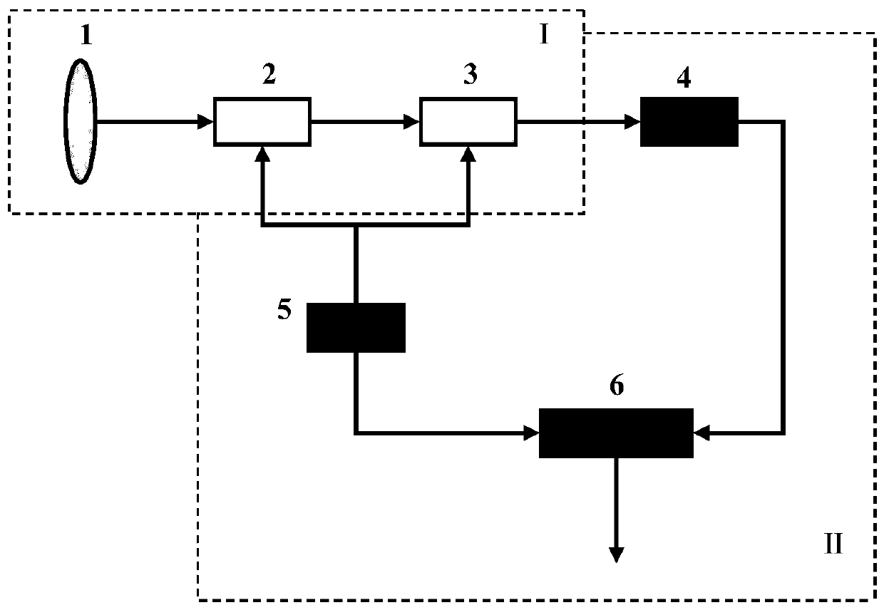
[0042] reference figure 1 , Embodiment 1 of the present invention provides a multi-scale modulation compressed sensing imaging system, which includes an optical unit I and an electrical unit II; wherein, the optical unit I includes an imaging lens 1, a multi-scale phase modulation component 2, an intensity modulation component 3; The electrical unit II includes an array detector 4, a control module 5, and a storage computing module 6.

[0043] The imaging lens 1 images the target to be imaged onto the array detector 4; during the transmission of the optical signal to the array detector 4, the multi-scale phase modulation component 2 performs phase modulation on the optical signal, and the intensity modulation component 3 performs intensity modulation on the optical signal The array detector 4 sends the spatial distribution of light intensity to the storage and calculation module 6; the storage and calculation module 6 is responsible for storing the phase modulation matrix and the ...

Embodiment 2

[0056] The above is the structural description of the multi-scale modulation compressed sensing imaging system of the present invention. The working process of the multi-scale modulation compressed sensing imaging system is described below.

[0057] Embodiment 2 of the present invention provides a multi-scale modulation compressed sensing imaging method, which includes:

[0058] Step 1) The steps of phase modulation and intensity modulation:

[0059] The control module 5 sends the phase modulation matrix and the intensity modulation matrix to the multi-scale phase modulation component 2 and the intensity modulation component 3, respectively, to realize the predetermined phase modulation and intensity modulation method; and transmits the phase modulation matrix and the intensity modulation matrix to all The storage calculation module 6;

[0060] Step 2) Steps for optical signal acquisition:

[0061] The imaging lens 1 images the target to be imaged onto the array detector 4; during the...


PUM


Abstract

The invention discloses a multi-scale modulation compressed sensing imaging system. The system comprises an optical unit (I) and an electrical unit (II). The optical unit (I) comprises an imaging lens(1), a multi-scale phase modulation part (2) and an intensity modulation part (3). The electrical unit (II) comprises an array detector (4), a control module (5) and a storage calculation module (6).The imaging lens (1) is used for imaging a to-be-imaged target to the array detector (4). The multi-scale phase modulation part (2) carries out phase modulation on the optical signal, and the intensity modulation part (3) carries out intensity modulation on the optical signal; the array detector (4) sends the light intensity distribution to the storage calculation module (6). The storage calculation module (6) calculates the corresponding relation between the light intensity distribution sent by the array detector (4) and the image of the to-be-imaged target, and performs image reconstructionby using a compressed sensing algorithm to obtain a reconstructed image of the to-be-imaged target.

Description

Technical field [0001] The invention relates to the field of optics, in particular to a multi-scale modulation compressed sensing imaging system and an imaging method thereof. Background technique [0002] Compressed sensing imaging is a computational imaging method whose theoretical basis is the compressed sensing sampling theory proposed in mathematics. In 2004, mathematicians such as Candès, Donoho and Tao proposed the compressed sensing sampling theory, which pointed out that a series of linear samples can be taken on the signal, and then the original signal can be accurately restored through the optimization algorithm. And compressed sensing sampling has sub-sampling capability, that is, the number of measurements can be less than the number of signals. In 2008, Baraniuk et al. realized compressed sensing imaging. Through random spatial modulation of the target image, and then compressed sensing reconstruction of the total intensity of the modulated image by the point detec...

Claims


Application Information

Patent Timeline
IPC IPC(8): H04N5/225H04B10/54H04B10/548
CPCH04B10/54H04B10/548H04N23/55
Inventor 刘雪峰姚旭日王小庆翟光杰
Owner NAT SPACE SCI CENT CAS
Learn More