Air interface signal alignment processing method, device and equipment and storage medium

An air interface signal and processing method technology, applied in the field of communication, can solve problems such as high buffer pressure of radio frequency units, and achieve the effect of reducing resource occupation and buffer pressure.

Active Publication Date: 2019-09-06
TD TECH COMM TECH LTD
View PDF12 Cites 2 Cited by
  • Summary
  • Abstract
  • Description
  • Claims
  • Application Information

AI Technical Summary

Problems solved by technology

[0005] The present application provides a processing method, device, equipment and storage medium for air interfa

Method used


Image

  • Air interface signal alignment processing method, device and equipment and storage medium
  • Air interface signal alignment processing method, device and equipment and storage medium
  • Air interface signal alignment processing method, device and equipment and storage medium

Examples


Example Embodiment

[0029] Embodiment one

[0030] This embodiment provides a method for processing air interface signal alignment, which is used for air interface signal alignment processing. The execution subject of this embodiment is an apparatus for processing air interface signal alignment, and the apparatus may be set in a processing device for air interface signal alignment, specifically, it may be set in a baseband unit.

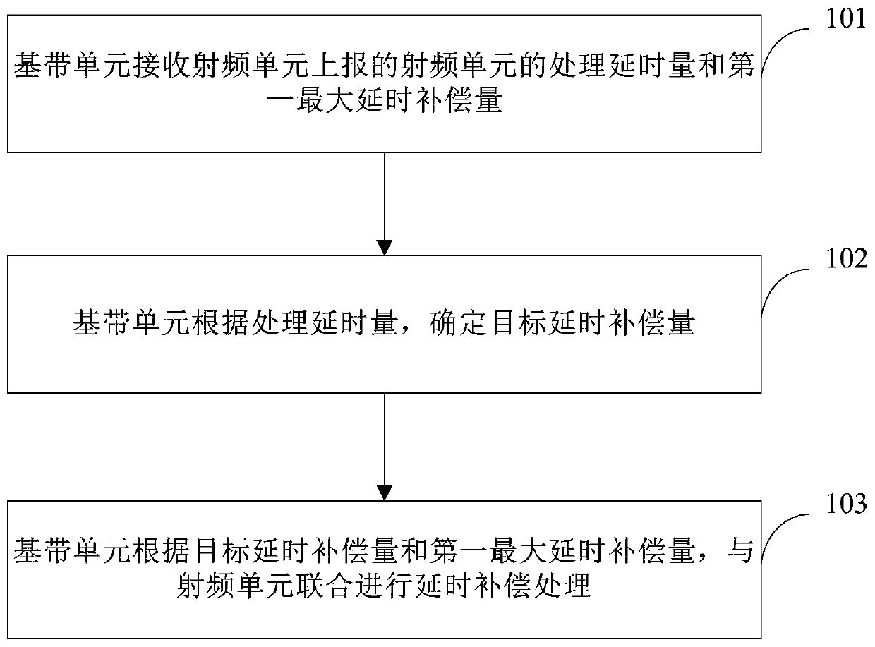
[0031] like figure 1 As shown, it is a schematic flow chart of the air interface signal alignment processing method provided in this embodiment, and the method includes:

[0032] Step 101, the baseband unit receives the processing delay amount of the radio frequency unit and the first maximum delay compensation amount reported by the radio frequency unit.

[0033] Specifically, each baseband unit may be connected to one or more radio frequency units through an optical fiber, and for each radio frequency unit, the radio frequency unit may report the processing delay an...

Example Embodiment

[0043] Embodiment two

[0044] This embodiment provides a further supplementary description of the method provided in the first embodiment.

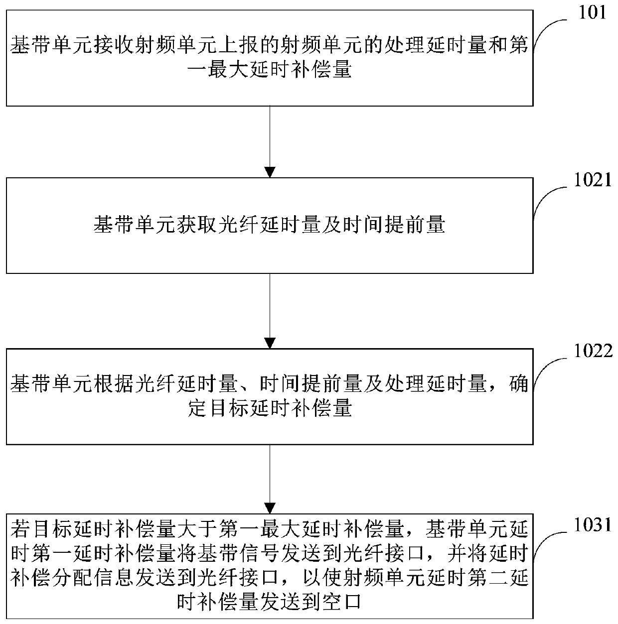
[0045] like figure 2 As shown in , it is a schematic flow chart of the processing method for air interface signal alignment provided in this embodiment.

[0046] As an implementable manner, on the basis of the foregoing embodiments, optionally, step 102 specifically includes:

[0047] Step 1021, the baseband unit acquires the fiber delay and timing advance.

[0048]The timing advance is the timing advance for the baseband unit to send the baseband signal to the optical fiber interface.

[0049] Step 1022, the baseband unit determines the target delay compensation amount according to the fiber delay amount, timing advance amount and processing delay amount.

[0050] Specifically, the baseband unit needs to send a specific baseband signal to the optical fiber interface with a certain amount of time advance, and transmit it to the radi...

Example Embodiment

[0066] Embodiment three

[0067] This embodiment provides a processing device for air interface signal alignment, which is used to execute the method in the first embodiment above.

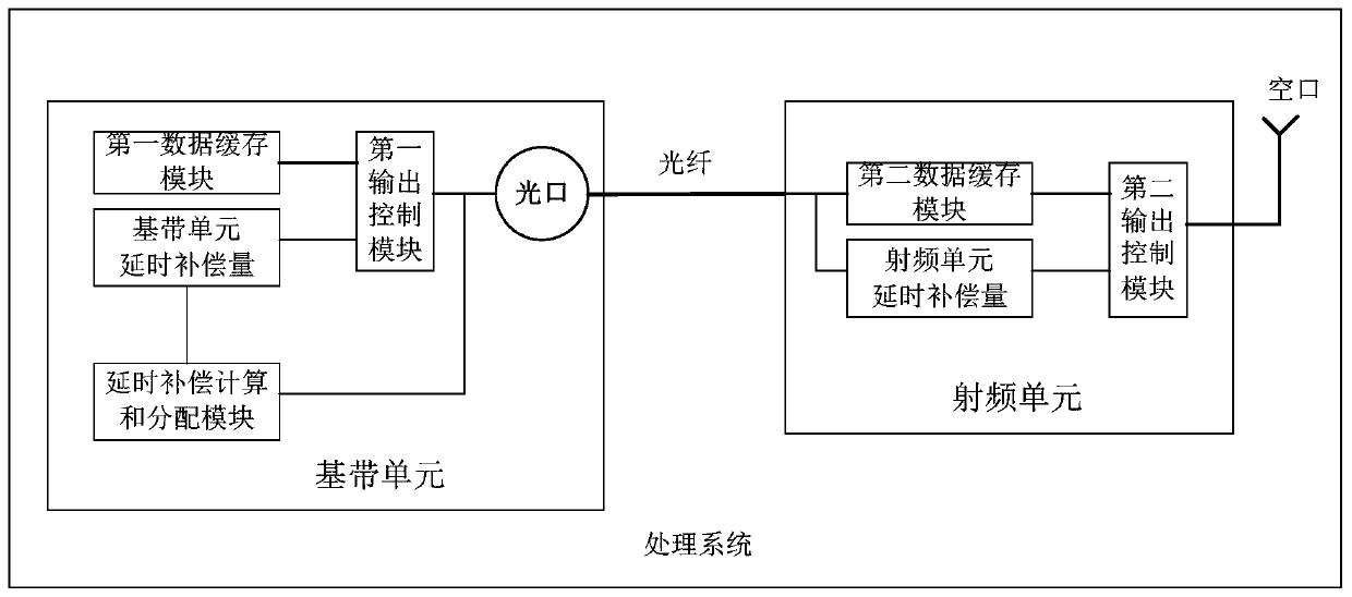
[0068] like Figure 4 As shown in , it is a schematic structural diagram of an air interface signal alignment processing device provided in this embodiment. The air interface signal alignment processing device 30 includes a receiving module 31 , a determining module 32 and a processing module 33 .

[0069] Wherein, the receiving module is used for the baseband unit to receive the processing delay amount and the first maximum delay compensation amount of the radio frequency unit reported by the radio frequency unit; the determination module is used for the baseband unit to determine the target delay compensation amount according to the processing delay amount; The processing module is used for the baseband unit to jointly perform delay compensation processing with the radio frequency unit accordi...


PUM


Abstract

The invention provides an air interface signal alignment processing method, device, equipment and a storage medium. The method comprises the following steps: a baseband unit receiving a processing delay amount and a first maximum delay compensation amount of a radio frequency unit reported by the radio frequency unit; the baseband unit determining a target delay compensation amount according to the processing delay amount; and the baseband unit being combined with the radio frequency unit to carry out delay compensation processing according to the target delay compensation amount and the firstmaximum delay compensation amount. Therefore, the baseband unit can share with the radio frequency unit for delay compensation, resource occupation of the radio frequency unit buffer is reduced, andthe buffer pressure of the radio frequency unit is reduced.

Description

technical field [0001] The present application relates to the technical field of communications, and in particular to a processing method, device, device and storage medium for air interface signal alignment. Background technique [0002] In the composition of the wireless base station, the baseband unit and the radio frequency unit are two independent network elements, and the two communicate through the optical fiber connection, and the radio frequency unit can be extended to any network coverage area through the optical fiber. When realizing the optical fiber remote function of the video unit, it is necessary to ensure that the signals transmitted to the air interface (air interface) by all base stations in the entire network are synchronized, which requires that the signal transmitted by the radio frequency unit to the air interface can be transmitted at any distance by optical fiber. Arrive at the same moment. For the baseband unit, on its input side, all user signals ...

Claims


Application Information

Patent Timeline
IPC IPC(8): H04W28/02H04W56/00H04B10/2575
CPCH04W28/0205H04W56/004H04B10/25752
Inventor 张永伟
Owner TD TECH COMM TECH LTD
Why Eureka
Try Eureka