Method and architecture for performing scrubbing of an FPGA's configuration memory

a configuration memory and fpga technology, applied in the field of methods, can solve the problems of small solution, and achieve the effect of reducing the usage of logical resources

Active Publication Date: 2012-12-11
MICROELECTRONICS RES DEV CORP
View PDF2 Cites 33 Cited by
  • Summary
  • Abstract
  • Description
  • Claims
  • Application Information

AI Technical Summary

Benefits of technology

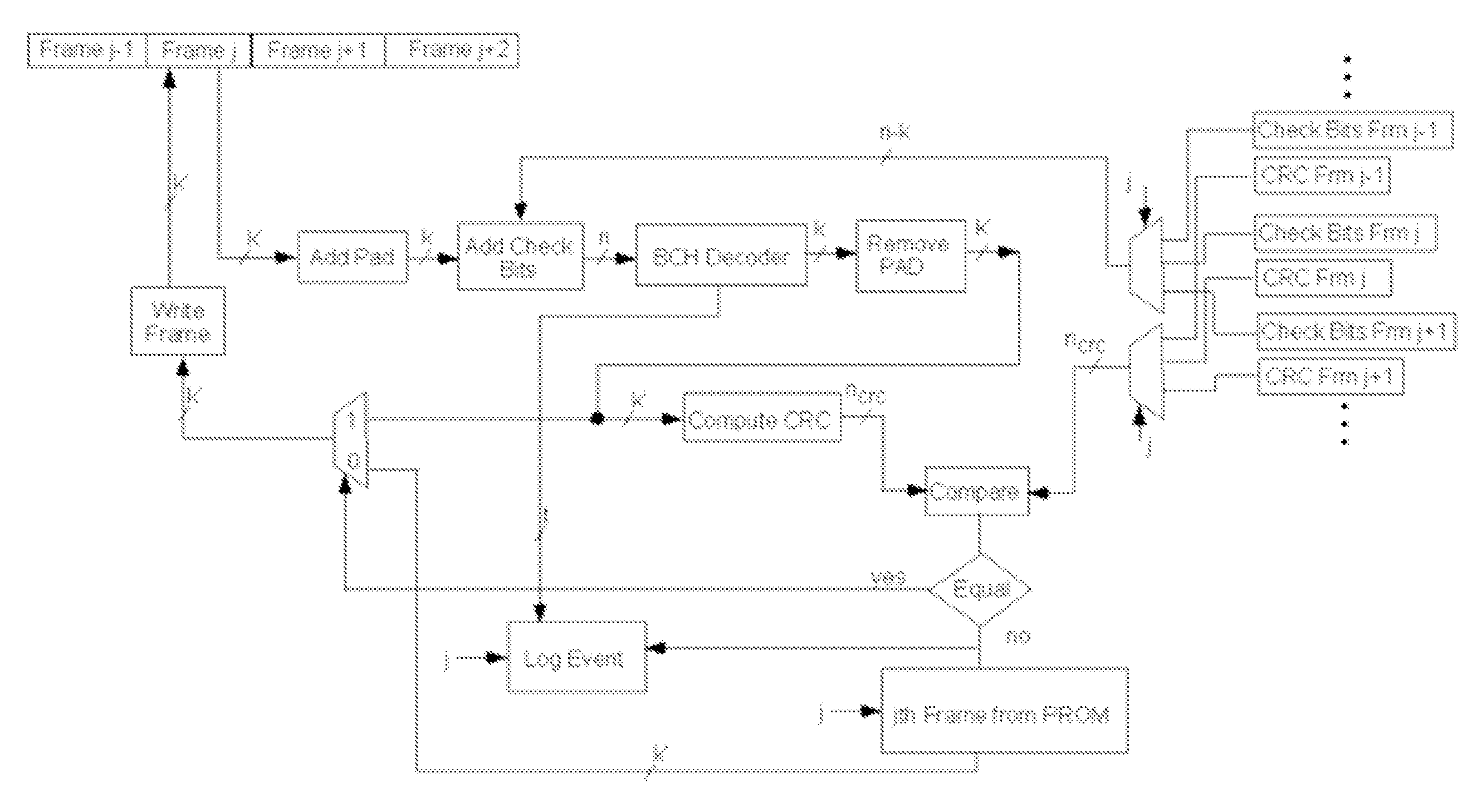
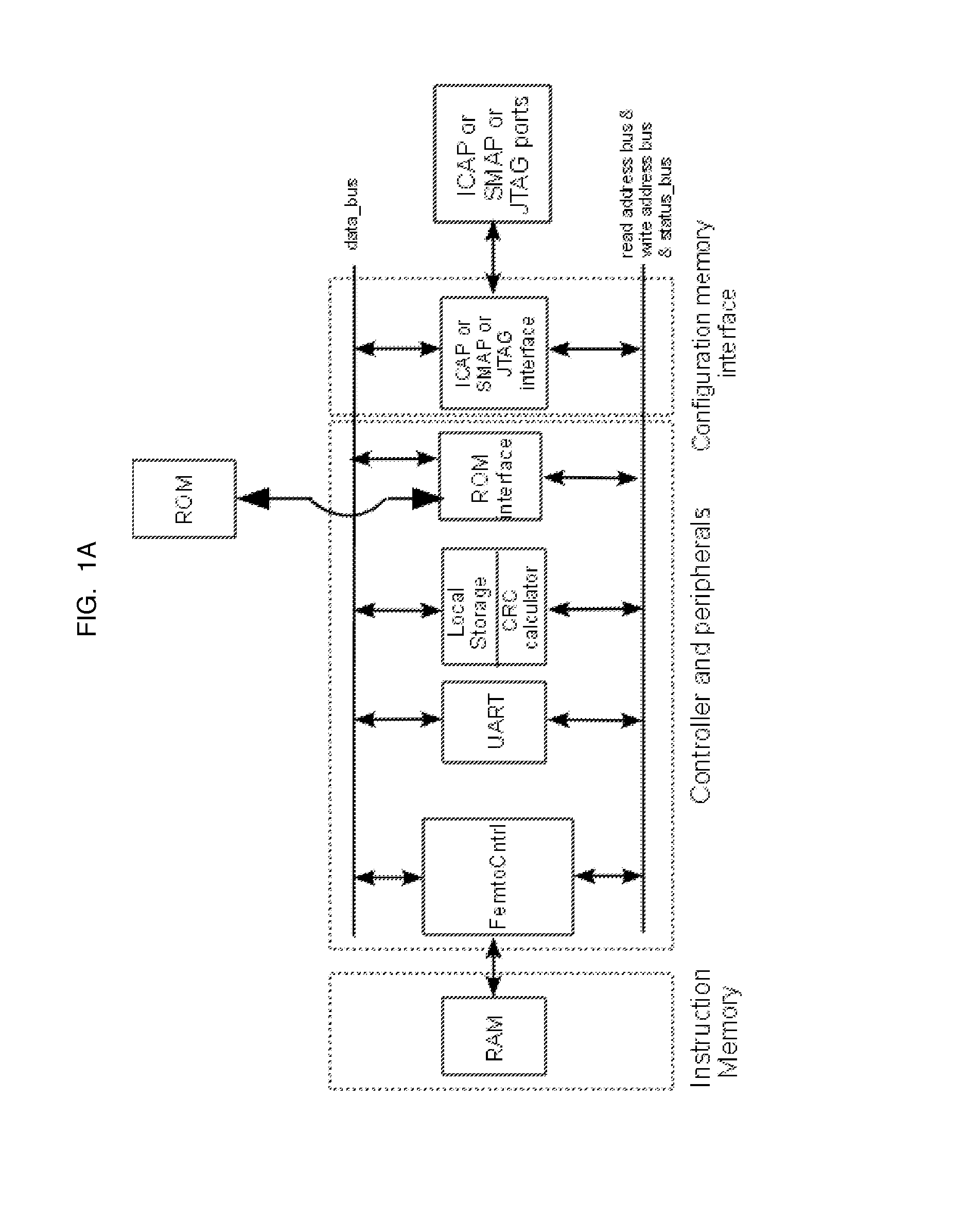
[0028]A scrubber solution is provided herein based on a small microcontroller which provides flexibility with reduced logical resources usage to detect and correct configuration errors within configurable logic devices, such as FPGAs.

Problems solved by technology

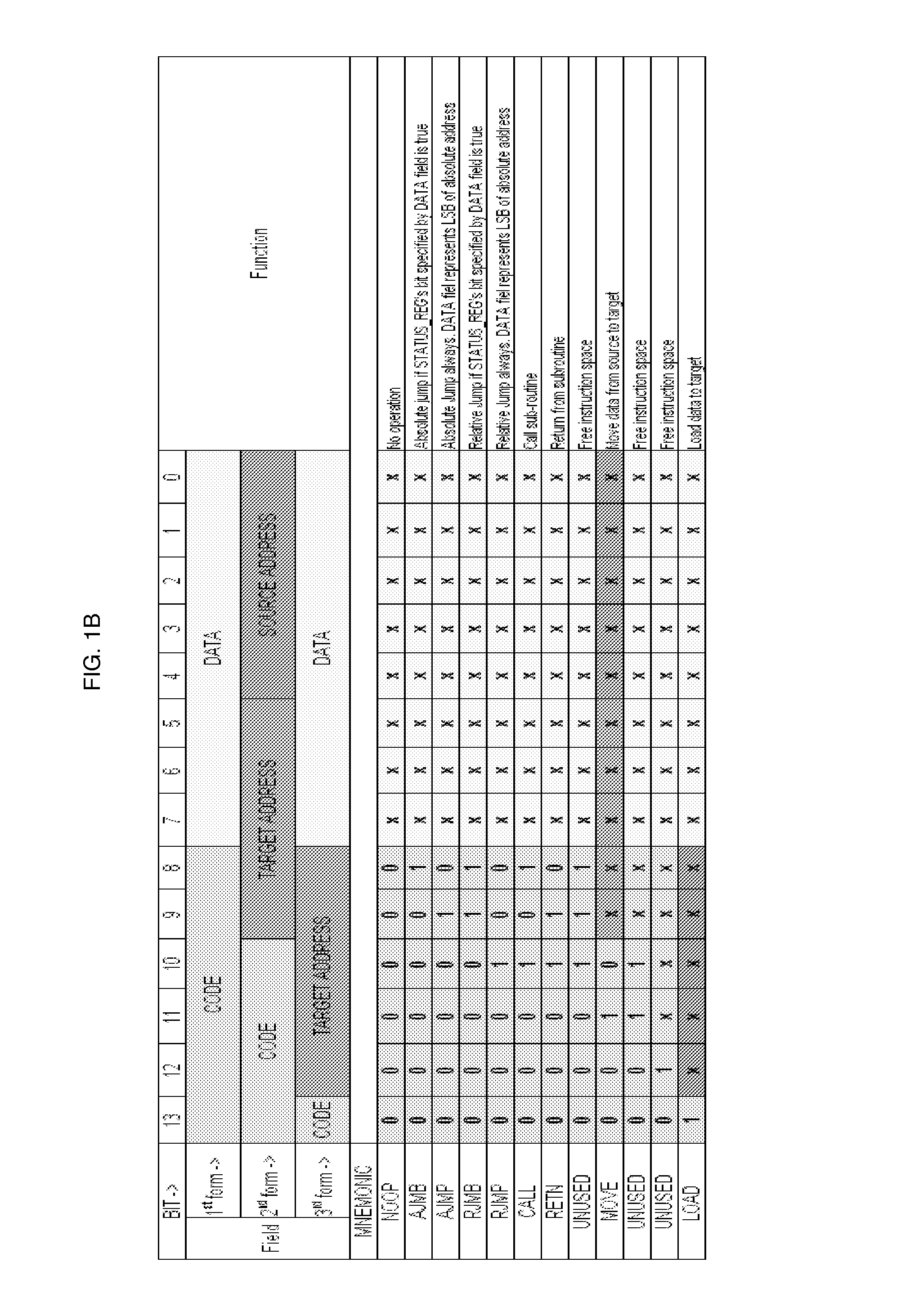
Although processor-based, this solution is smaller than currently picoblaze-based solutions due to its restrictive set of instructions.

Method used


Image

  • Method and architecture for performing scrubbing of an FPGA's configuration memory
  • Method and architecture for performing scrubbing of an FPGA's configuration memory
  • Method and architecture for performing scrubbing of an FPGA's configuration memory

Examples


example

Minimal Level Sensitive Latch

[0123]Referring now to FIG. 9, an example of an application of temporal sampling is provided. One way to describe a level sensitive transparent latch is as a two-input MUX (multiplexer) with its output fed back to one of its inputs, the data fed to its other input, and the select line controlled by the clock signal. Since this is really just a standard combinatorial logic gate, it should be possible to use temporal sampling to replicate the function of the MUX in time and achieve the same SEU immunity as if it were replicated spatially. In this way, temporal sampling achieves the equivalent of triple spatial redundancy by simply reusing the same MUX at three different times.

[0124]FIG. 9 shows how this is accomplished. Rather than feed the MUX output directly back to one of its inputs, we first sample the MUX (U1) output using a voting circuit (U2) along with sampling delays (U3 and U4) and then feed the majority of the sampled data back to the input. Eve...


PUM


Abstract

This invention relates to device and methods for scrubbing configurable logic devices that are used in high-radiation environments.

Description

CROSS REFERENCE TO RELATED APPLICATIONS[0001]This application is a continuation and claims priority benefit under 35 USC 120 to U.S. application Ser. No. 12 / 854,887, filed 11 Aug. 2010 now abandoned, the contents of which are incorporated herein in their entirety.STATEMENT REGARDING FEDERALLY SPONSORED RESEARCH OR DEVELOPMENT[0002]This invention was made with Government support under contract FA9453-08-M-0096 awarded by the U.S. Air Force / Research Lab. The Government has certain rights in the invention.NAMES OF PARTIES TO A JOINT RESEARCH AGREEMENT[0003]Not applicable.SEQUENCE LISTING INCLUDED AND INCORPORATED BY REFERENCE HEREIN[0004]Not applicable.BACKGROUND[0005]1. Field of the Invention[0006]This invention relates to processes and microcontrollers for scrubbing, or removing errors from, a computer memory's content by re-writing it periodically with correct values.[0007]2. Background of the Invention[0008]A Field Programmable Gate Array (FPGA) is an integrated circuit which is co...

Claims


Application Information

Patent Timeline
Patent Type & Authority Patents(United States)
IPC IPC(8): H03M13/00
CPCH03M13/3776G06F11/106H03K19/17764H03K19/17768H03M13/09H03M13/096H03M13/152G11C2029/0409
Inventor VERA ROJAS, GUILLERMO ALONZOARDALAN, SASAN
Owner MICROELECTRONICS RES DEV CORP
Why Eureka
Try Eureka