Three-claw inner support clamp assembly

A technology for inner support fixtures and components, used in clamping, manufacturing tools, metal processing mechanical parts, etc., can solve the problems of inability to carry heavy loads, poor self-locking ability of ball screws, and achieve the effect of ensuring the pressing force

Pending Publication Date: 2019-09-10
南京合信智能装备有限公司
View PDF10 Cites 11 Cited by
  • Summary
  • Abstract
  • Description
  • Claims
  • Application Information

AI Technical Summary

Problems solved by technology

However, the self-locking ability of the ball screw

Method used


Image

  • Three-claw inner support clamp assembly
  • Three-claw inner support clamp assembly
  • Three-claw inner support clamp assembly

Examples


Embodiment Construction

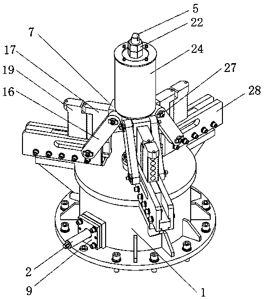
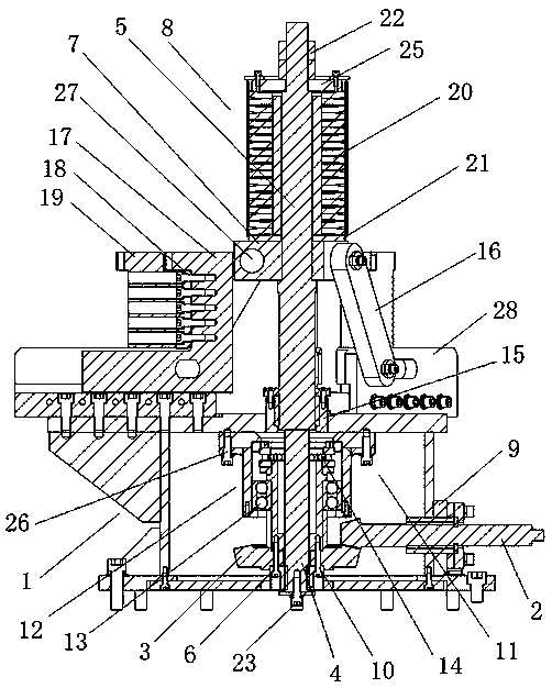
[0023] For further illustrating the present invention, below in conjunction with appendix Figure 1-2 To explain:

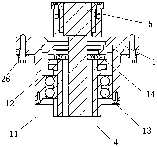
[0024] A three-jaw internal support fixture assembly includes a support frame 1, a small bevel gear shaft 2, a large bevel gear 3, a first screw 4, a second screw 5, a screw nut 6, a connecting block 7, and a disc spring 8. One side of the support frame 1 is provided with a fixed seat 9 with an opening in the middle. Through the fixed seat 9, the support frame 1 is rotatably connected to the small bevel gear shaft 2, and the small bevel gear shaft 2 is engaged with the large bevel gear 3 located in the center of the support frame 1. Transmission, the large bevel gear 3 is connected with the lead screw nut 6 through the first screw 10.

[0025] The bottom of the first lead screw 4 passes through the lead screw nut 6 and is threadedly connected with the lead screw nut 6 , and the lead screw nut 6 is rotatably installed at the center of the base of the support fram...


PUM


Abstract

The invention discloses a three-claw inner support clamp assembly. A supporting frame, a small bevel gear shaft, a large bevel gear, a first lead screw, a second lead screw, a lead screw nut, a connecting block and a disc spring are included. A fixing base with a middle opening is arranged on one side of the supporting frame. The small bevel gear shaft is in meshing transmission with the large bevel gear located at the center position of the supporting frame. The large bevel gear is in transmission connection with the lead screw nut through a first screw. The first lead screw and the second lead screw are fixedly connected and combined into an ejector rod lead screw. A guiding base is located above a bearing block, and rotation of the ejector rod lead screw is limited through cooperation of a guiding key in the guiding base and a key groove in the surface of the second lead screw. The rotating power of the small bevel gear shaft drives the large bevel gear to rotate through cooperationof the small bevel gear shaft and the large bevel gear, the lead screw nut connected with the large bevel gear drives the ejector rod lead screw to ascend and descend at the same time so that a sliding block can be driven to move in the horizontal direction, accordingly, axial force is further converted into horizontal force, and the function of workpiece pressing is achieved.

Description

technical field [0001] The invention relates to the field of mechanical tooling, in particular to a three-jaw inner support clamp assembly. Background technique [0002] The screw nut mechanism, also known as the screw transmission mechanism, can convert the rotational motion of the nut into the linear motion of the screw to transmit the axial force. If it is in a small closed space and there are objects around it, the space for turning the nut will be limited, and the function of transmitting axial force cannot be realized. In the Chinese invention patent spiral bevel gear ball screw lift (CN2016200417349), a spiral bevel gear ball screw lift is disclosed, including a box body, a power input shaft is rotatably installed on the box body, and the first end of the power input shaft Extending out of the box, the second end of the power input shaft is located in the box; the second end is fixedly connected with a spiral bevel gear; the box is rotatably installed with a ball scr...

Claims


Application Information

Patent Timeline
IPC IPC(8): B23Q3/06
CPCB23Q3/062
Inventor 薛建文周曙君梅庆峰周超戴冬生靳玉新
Owner 南京合信智能装备有限公司
Why Eureka
Try Eureka