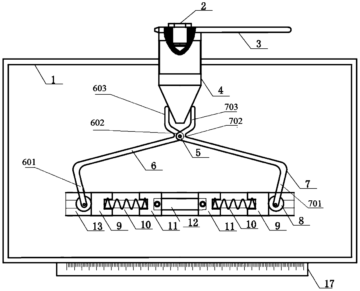
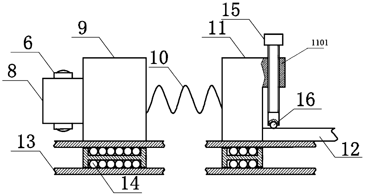
Temperature-compensated deep-cold laser impact experimental fixture

A technology of laser shock and temperature compensation, which is applied in laser welding equipment, manufacturing tools, welding equipment, etc., can solve problems such as decreased accuracy of strengthening, plastic shrinkage deformation, and dangerous experimental operations, and achieves simple structure, improved repeatability, and The effect of improving efficiency and safety

Active Publication Date: 2019-08-23
JIANGSU UNIV
View PDF8 Cites 3 Cited by
  • Summary
  • Abstract
  • Description
  • Claims
  • Application Information

AI Technical Summary

Problems solved by technology

[0003] However, cryogenic laser shock strengthening requires the sample to reach a cryogenic temperature during the experiment, and the metal material will undergo plastic shrinkage and deformation in the ultra-low temperature environment for a long time, so that the conventional fixture cannot guarantee the complete clamping of the sample during the impact process.
In addition, the experimental operation in the cryogenic environment is more dangerous, and the clamping process of the experimental sample is inefficient, so the fixtures used in the traditional laser shock system are not suitable for the cryogenic environment
For example, the prior art proposes a universal fixture for laser shock strengthening of flat samples, which mainly fixes the sample by tightening bolts, but the fixture will not be able to clamp the sample after the sample shrinks at cryogenic temperature. tight action
[0004] However, the existing cryogenic laser shock strengthening devices are all aimed at cryogenic devices and do not specifically consider the special fixture for cryogenic laser shock
In the cryogenic laser shock strengthening device of the prior art, the sample is generally placed directly on the cryogenic workbench to cool down through heat conduction without clamping, which will cause the movement of the sample during the impact process and reduce the accuracy of strengthening

Method used


Image

  • Temperature-compensated deep-cold laser impact experimental fixture
  • Temperature-compensated deep-cold laser impact experimental fixture

Examples


Embodiment Construction

[0031] Embodiments of the present invention are described in detail below, examples of which are shown in the drawings, wherein the same or similar reference numerals designate the same or similar elements or elements having the same or similar functions throughout. The embodiments described below by referring to the figures are exemplary and are intended to explain the present invention and should not be construed as limiting the present invention.

[0032] In describing the present invention, it is to be understood that the terms "central", "longitudinal", "transverse", "length", "width", "thickness", "upper", "lower", "axial", The orientation or positional relationship indicated by "radial", "vertical", "horizontal", "inner", "outer", etc. is based on the orientation or positional relationship shown in the drawings, and is only for the convenience of describing the present invention and simplifying the description , rather than indicating or implying that the device or elem...


PUM

PropertyMeasurementUnit
lengthaaaaaaaaaa
thicknessaaaaaaaaaa

Abstract

The invention provides a temperature-compensated deep-cold laser impact experimental fixture. The temperature-compensated deep-cold laser impact experimental fixture comprises a spring and sliding block compression piece and a camping piece, wherein the spring and sliding block compression piece comprises two identical spring and sliding block units, each spring and sliding block unit comprises anouter sliding block, a spring and an inner sliding block, each spring is connected with the corresponding outer sliding block and the corresponding inner sliding block, and each outer sliding block and each inner sliding block can slide along the straight line; and the clamping piece is used for clamping the two outer sliding blocks from the outer side surfaces of the two outer sliding blocks, the two spring and sliding block compression pieces are located on the same straight line and symmetrically distributed, and under the action of the clamping piece, the two inner sliding blocks can clamp a sample workpiece from the two ends of the sample workpiece. The temperature-compensated deep-cold laser impact experimental fixture can actively compensate for the plastic shrinkage of the samplein the deep-cold environment in real time, and the clamping force of the fixture to the sample in the reinforcement process is ensured all the time.

Description

technical field [0001] The invention relates to the technical field of laser processing and surface strengthening, in particular to a temperature-compensated cryogenic laser shock experiment fixture. Background technique [0002] Cryogenic laser shock peening technology combines the multiple advantages of laser shock peening high-energy ultrafast and ultra-low temperature deformation technology. The yield strength of materials at cryogenic temperatures is significantly improved. Therefore, compared with traditional laser shock, cryogenic laser shock peening can be used on metal materials. The surface induces higher residual compressive stress amplitude and higher density dislocation structure, and further refines the surface grains, thereby significantly improving the fatigue resistance of structural parts. Extremely broad application prospects. [0003] However, cryogenic laser shock strengthening requires the sample to reach a cryogenic temperature during the experiment, ...

Claims


Application Information

Patent Timeline
Patent Type & Authority Applications(China)
IPC IPC(8): B23K26/352B23K26/356B23K26/70
CPCB23K26/352B23K26/356B23K26/70B23K26/702
Inventor 马敏周建忠孙昀杰李京孟宪凯田绪亮黄宇
Owner JIANGSU UNIV
Why Eureka
Try Eureka