
Cranked plate hole-boring clamp

A technology of boring fixture and bending chain, which is applied in the field of bending chain plate boring fixture, can solve the problems of cutting speed and cutting amount limitation, affecting workpiece aperture surface roughness and aperture dimensional accuracy, and reducing processing efficiency, so as to improve the aperture Effects of surface roughness and dimensional accuracy of hole diameter, improvement of machining accuracy and surface roughness, and improvement of cutting speed

Active Publication Date: 2018-08-10
ANHUI HUANGSHAN HENGJIU CHAIN TRANSMISSION CO LTD
View PDF10 Cites 4 Cited by
  • Summary
  • Abstract
  • Description
  • Claims
  • Application Information

AI Technical Summary

Problems solved by technology

Before boring, clamp two curved chain plates at one time. Due to the thickness difference between the two curved chain plates, the range of thickness difference is 0-1.5mm. The contact between them is mostly line contact. The pressing force of the flat platen on the workpiece will shift the position of the hole, resulting in a greatly reduced pressing force. When encountering cutting resistance, the workpiece is easy to vibrate, causing vibration marks on the surface of the workpiece aperture, which in turn affects The surface roughness of the workpiece aperture and the dimensional accuracy of the aperture; at the same time, due to the reduction of the pressing force, the cutting speed and cutting amount are limited, which greatly reduces the processing efficiency
In addition, the bending height of the two curved chain plates in one clamping will also be different, the range of height difference is 0-2mm, the height of the equal height block is generally determined according to the actual height average value of the same batch of curved chain plates after bending , the median value of the actual height of the same batch of bent chain plates is usually selected. However, when the height of the bent plate chain is smaller than the block of equal height, the aperture of the processed product is not perpendicular to the plane of the bent chain plate, and there is a pitch error. The height of the bent plate chain When it is higher than the equal height block, the support will be unstable. When encountering cutting resistance, the workpiece will easily vibrate, which will also affect the surface roughness and dimensional accuracy of the workpiece aperture. Assembled and scrapped

Method used


Image

  • Cranked plate hole-boring clamp
  • Cranked plate hole-boring clamp
  • Cranked plate hole-boring clamp

Examples


Embodiment Construction

[0020] The following will clearly and completely describe the technical solutions in the embodiments of the present invention with reference to the accompanying drawings in the embodiments of the present invention. Obviously, the described embodiments are only part of the embodiments of the present invention, not all of them. Based on the embodiments of the present invention, all other embodiments obtained by persons of ordinary skill in the art without making creative efforts belong to the protection scope of the present invention.

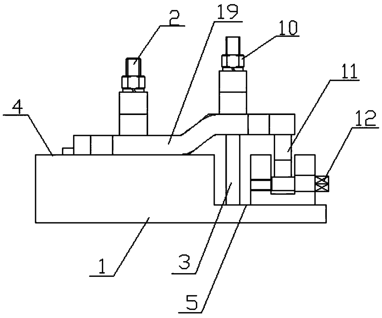
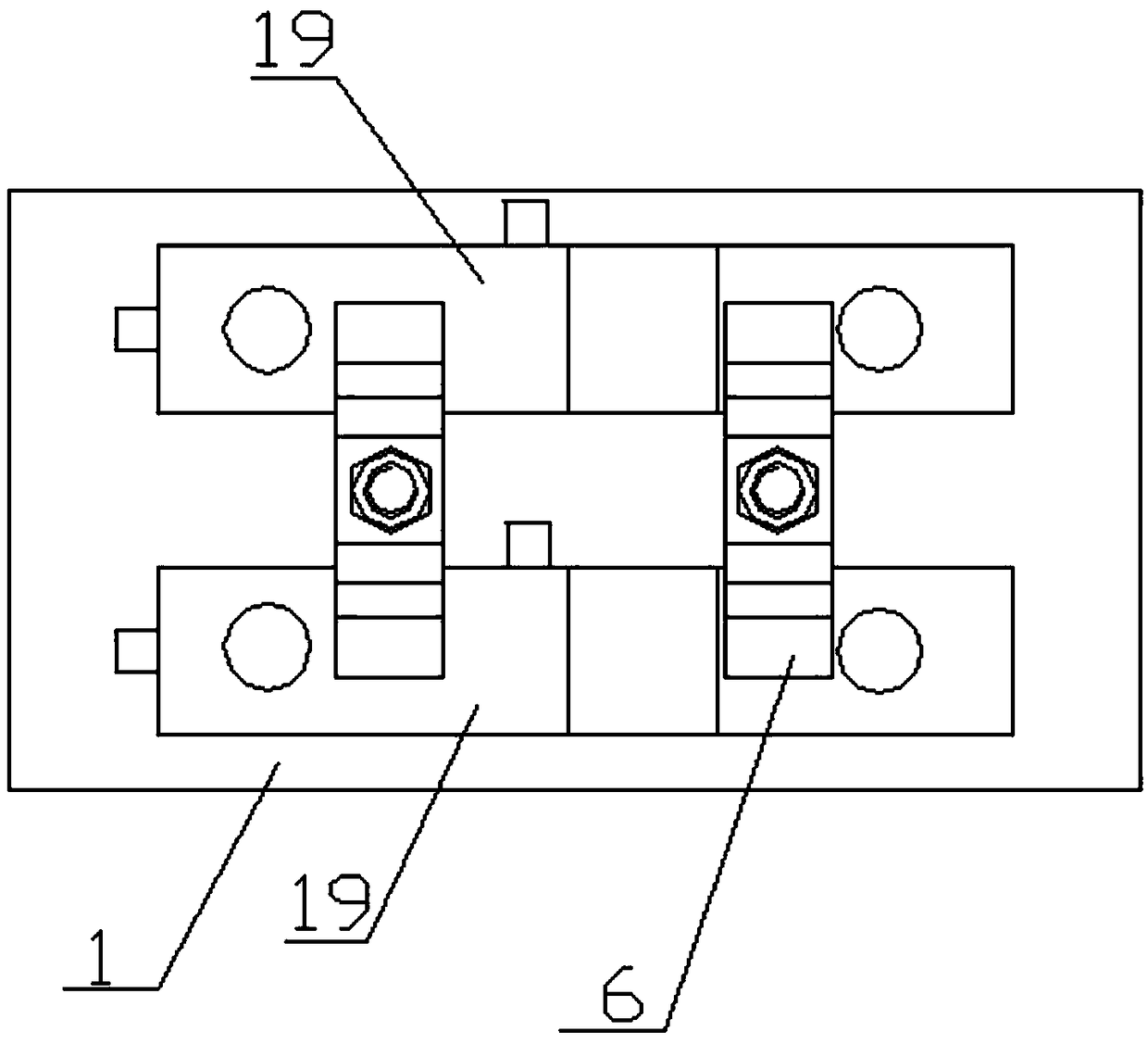
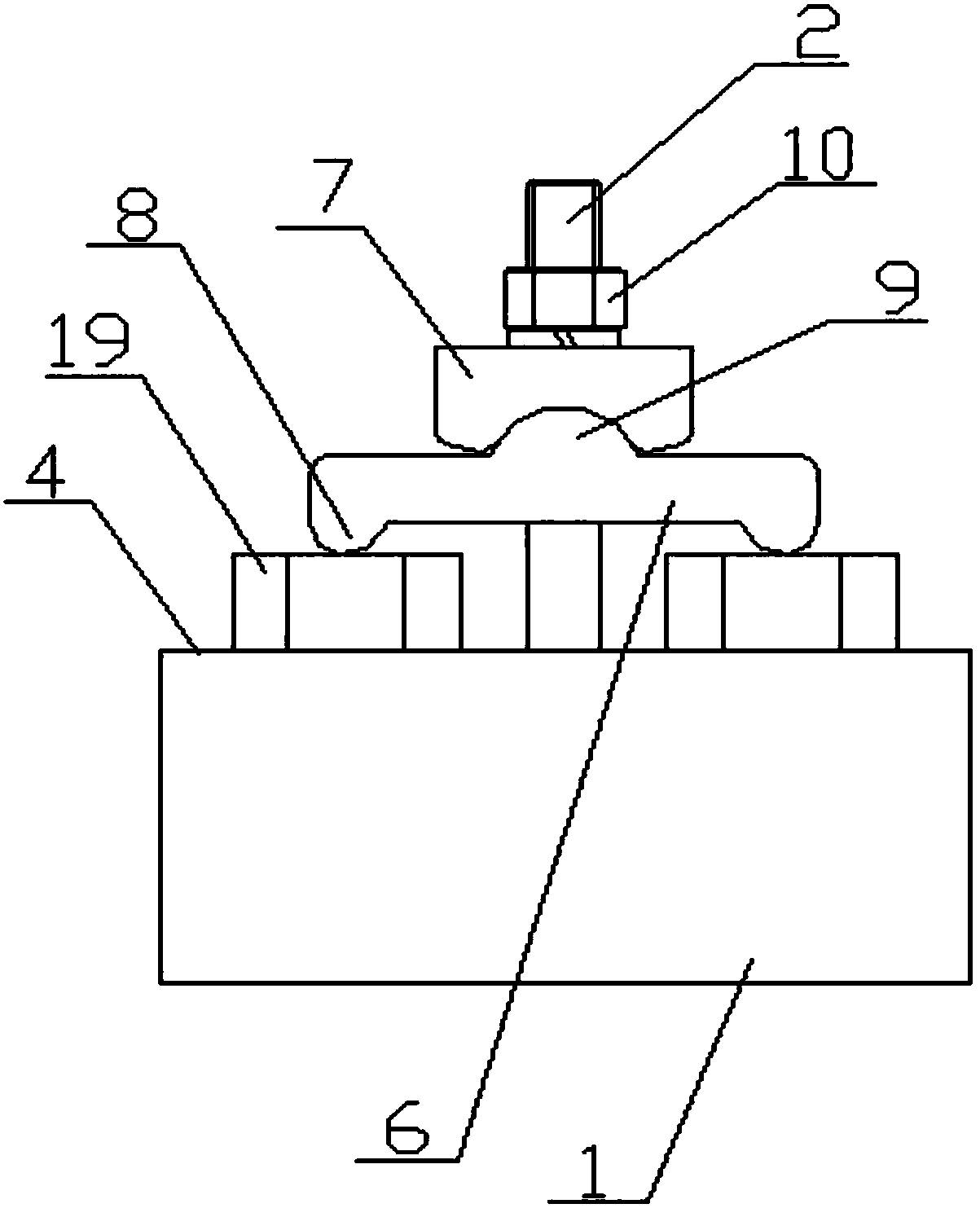
[0021] see Figure 1-7 As shown, a bending fixture for chain plate boring includes a base 1, a first screw 2, a second screw 3, a floating self-positioning device and two floating pressing devices, and the base 1 is provided with a first workpiece support surface 4 and the second workpiece supporting surface 5 whose height is lower than the first workpiece supporting surface 4, the floating pressing device includes a floating pressing plate 6 and...


PUM


Abstract

The invention discloses a cranked plate hole-boring clamp. The cranked plate hole-boring clamp comprises a base, a first threaded rod, a second threaded rod, a floating self-positioning device and twofloating pressing devices. The base is provided with a first workpiece supporting surface and a second workpiece supporting surface, and the height of the second workpiece supporting surface is lessthan that of the first workpiece supporting surface. Each floating pressing device comprises a floating pressing plate and a pressing cushion block. The two sides of the lower end surface of each floating pressing plate are provided with pressing plate supporting parts correspondingly. The upper end faces of the floating pressing plates are provided with arc surface protrusions. The lower end faces of the pressing cushion blocks are provided with positioning grooves matched with the arc surface protrusions. The lower end of the first threaded rod sequentially penetrates through a locking nut,the corresponding pressing cushion block and the corresponding floating pressing plate and then is connected to the first workpiece supporting surface. The lower end of the second threaded rod sequentially penetrates through a locking nut, the corresponding pressing cushion block and the corresponding floating pressing plate and then is connected to the second workpiece supporting surface. The cranked plate hole-boring clam can clamp two to-be-machined workpieces at a time, and the machining precision of the workpieces can be improved.

Description

technical field [0001] The invention relates to the technical field of chain production, in particular to a boring jig for a bent chain plate. Background technique [0002] Bending plate chain is one of the chains that have been widely used in the market at present. The bending plate chain is composed of a bending plate, a sleeve and a pin shaft. The large hole of the bending plate is in interference fit with the sleeve. The pin shaft is interference fit. When processing the curved chain plate, it must be ensured that the large and small holes of the adjacent two curved chain plates must be concentric before assembly. At present, when the bent chain plate to be processed is bored, it is basically pressed by a common flat plate, and is supported by a block of equal height according to the height difference between the two ends of the bent chain plate after bending. Before boring, clamp two curved chain plates at one time. Due to the thickness difference between the two curve...

Claims


Application Information

Patent Timeline
Patent Type & Authority Applications(China)
IPC IPC(8): B23Q3/06B23Q3/10
CPCB23Q3/062B23Q3/10B23Q2703/10Y02P70/10
Inventor 张可飞章媛王晓龙周子棠
Owner ANHUI HUANGSHAN HENGJIU CHAIN TRANSMISSION CO LTD
Learn More