

Improved concrete vibrating cylinder
A concrete and vibrating cylinder technology, applied in the field of concrete vibrating cylinders, can solve the problems of difference in vibration degree, large degree of segregation, inconvenient use, etc., achieve the effect of perfect internal structure and reduce segregation phenomenon
- Summary
- Abstract
- Description
- Claims
- Application Information
AI Technical Summary
Problems solved by technology
Method used
Image

Examples
Embodiment Construction
[0021] The present invention will be further described below in conjunction with the accompanying drawings.
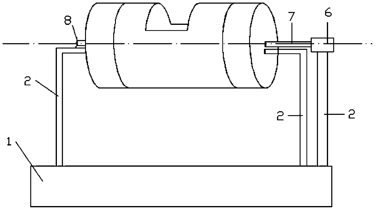
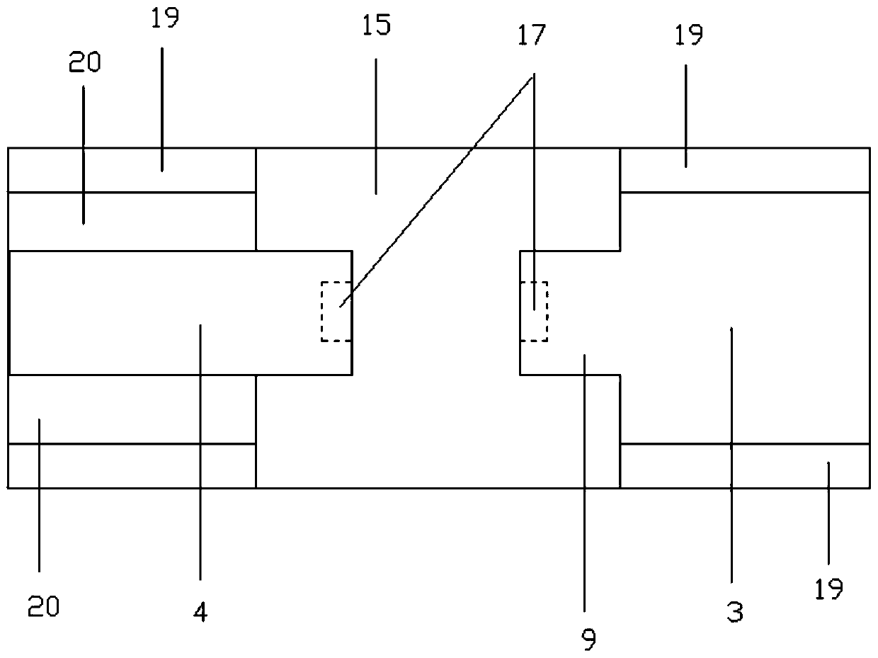
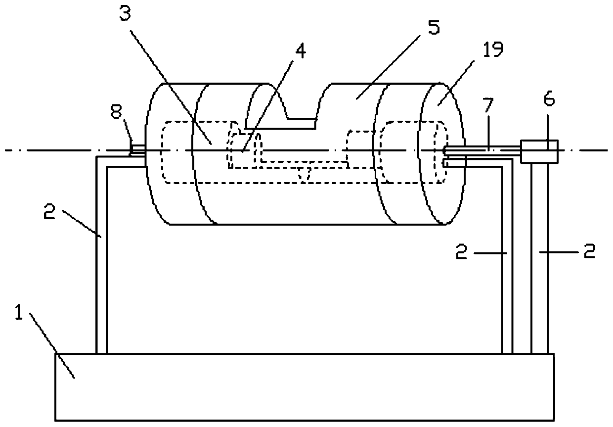
[0022] refer to Figure 1 to Figure 7 , an improved concrete vibrating cylinder, including a vibrating table 1, a fixed rod 2, an outer cylinder 5 and a rotating cylinder 3, the vibrating table 1 is connected with the outer cylinder 5 through the fixed rod 2, and the outer cylinder 5 is provided with a rotating cylinder 3, the outer wall of the rotating cylinder 3 and the inner wall of the outer cylinder 5 are unconstrainedly connected, the left half of the rotating cylinder 3 is connected to the right half through the connecting arm 11, the right half of the rotating cylinder The outer end of the part is connected with the rotating shaft 7, and the rotating shaft 7 is connected with the output shaft of the rotating motor 6, and the rotating motor 6 is connected on the vibrating table 1 through a fixed rod, and the inner end of the right half of the rotating cylinder i...
PUM
 Abstract
Description
Claims
Application Information