Tension damper

A damper and tension technology, which is applied in the direction of winding strips, conveying filamentous materials, thin material processing, etc., can solve the problem that the damping force output control curve cannot maintain linearity, etc., to increase the output adjustment range and improve The effect of production quality

Inactive Publication Date: 2019-09-10
YANGTZE UNIV COLLEGE OF TECH & ENG
View PDF30 Cites 10 Cited by
  • Summary
  • Abstract
  • Description
  • Claims
  • Application Information

AI Technical Summary

Problems solved by technology

Chinese patent document CN107324144A describes a tension adjustment device, which can adjust the width with a large damping force, but the installation method of this scheme can only maintain the structure of the vertical axis, and is affected by factors such as eddy currents and evaporation, and the damping force is limited. Output control curve fails to maintain linearity

Method used


Image

  • Tension damper
  • Tension damper
  • Tension damper

Examples


Embodiment Construction

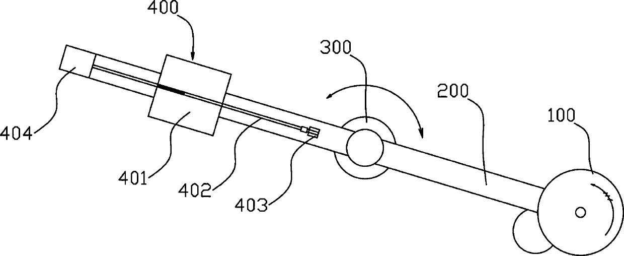
[0037] Such as figure 1 Among them, a tension damper, the balance bar 200 is rotatably installed on the balance base 300, and the balance base 300 is provided with an angle sensor for detecting the rotation angle of the balance bar 200; the set angle sensor is actually used for feedback on the wire or The tension of the strip 700 varies.

[0038] Bounded by the rotation axis of the balance base 300, a damper 100 is provided at one end of the balance pole 200, and the damper 100 is used to provide resistance for the wire or strip 700 to travel;

[0039] The other end of the balance bar 200 is provided with a slider device 400 that can adjust its position along the balance bar 200 . This structure can provide high-precision tension and high-precision resistance for the wire or strip 700 .

[0040] The preferred solution is as figure 1 In the slider device 400 described above, the counterweight slider 401 is slidably connected to the balance bar 200 , the screw rod 402 is rotat...


PUM


Abstract

The invention provides a tension damper. A balance bar is rotatably mounted on a balance base. An angle sensor used for detecting the rotation angle of the balance bar is arranged on the balance base.With the rotation axis of the balance base as a boundary, a damper body is arranged at one end of the balance bar and is used for providing advancing resistance for a wire or strip; and a sliding block device is arranged at the other end of the balance bar, and the position of the sliding block device can be adjusted along the balance bar. According to the tension damper, the tension applied to the wire or strip can be accurately adjusted through the structure of the balance bar, and thus, the tension damper can be applied to a wire or strip production line with a high precision requirement;and the resistance of the wire or strip can be controlled to keep the advancing speed of the wire or strip constant while the tension is controlled, the tension borne by the wire or strip is kept constant, and thus, the production quality of high-precision wires or strips is improved.

Description

technical field [0001] The invention relates to the field of tension dampers, in particular to a tension damper with adjustable damping force. Background technique [0002] The winding process is often involved in spinning, wire or strip production. In this process, the winding device is driven to rotate by the driving device, but as the diameter of the winding package increases, the pulling force applied by the package to the wire or strip A change occurs, usually increasing, which causes quality problems in the wire or strip, such as the wire or strip being stretched. A tensioner is usually used to keep the tension on the wire or strip constant. [0003] Known tensioners commonly used in spinning, wire or strip production usually use gravity or spring tensioners. The problem with these tensioners is that tension adjustment is relatively difficult. [0004] In the production process, the winding operation is involved. In order to ensure the uniform winding of the wire or ...

Claims


Application Information

Patent Timeline
Patent Type & Authority Applications(China)
IPC IPC(8): B65H23/188B65H59/16
CPCB65H23/1888B65H59/16B65H2701/11332B65H2701/35
Inventor 马秀花
Owner YANGTZE UNIV COLLEGE OF TECH & ENG
Why Eureka
Try Eureka