Plugging fireproof and explosion-proof structure of valve side casing pipe of converter transformer in converter station

A technology of converter transformers and explosion-proof structures, which is applied to building components, building structures, buildings, etc., can solve the problems of fire and explosion-proof performance, electromagnetic isolation effect and sealing performance, etc., and achieve good electromagnetic isolation effect, good explosion-proof performance, Guarantees the effect of sealing performance

Active Publication Date: 2019-09-10
应急管理部四川消防研究所 +1
View PDF6 Cites 9 Cited by
  • Summary
  • Abstract
  • Description
  • Claims
  • Application Information

AI Technical Summary

Problems solved by technology

[0003] The technical problem to be solved by the present invention is to provide a fire-proof and explosion-proof structure for the valve-side casing of the converter transformer in the converter station to solve the fire-proof and explosion-proof performance, electromagnetic isolation effect, and sealing performance of the converter bushing installation in the prior art suboptimal problem

Method used


Image

  • Plugging fireproof and explosion-proof structure of valve side casing pipe of converter transformer in converter station
  • Plugging fireproof and explosion-proof structure of valve side casing pipe of converter transformer in converter station
  • Plugging fireproof and explosion-proof structure of valve side casing pipe of converter transformer in converter station

Examples


Embodiment Construction

[0027] The present invention will be further described below with reference to the accompanying drawings and embodiments, and the mode of the present invention includes but not limited to the following embodiments.

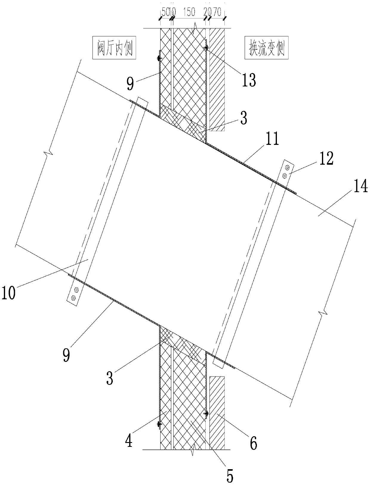
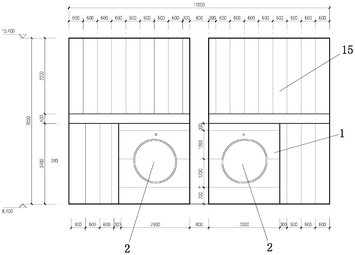
[0028] Such as Figure 1-4As shown, the present invention provides a fire-proof and explosion-proof structure for the plugging of the converter transformer valve side bushing in the converter station, which has a simple structure, scientific and reasonable design, and is easy to use. Well, the sealing performance is ideal. The present invention includes a fireproof and explosion-proof plate 1 sealed and installed on the fireproof wall 15 of the valve hall of the power station. The center of the fireproof and explosion-proof plate 1 is provided with a converter bushing installation hole 2 that matches the converter bushing 14. The installation holes 2 of the converter bushing are distributed obliquely, and the inclination thereof is consistent with the gradient of...


PUM

PropertyMeasurementUnit
Thicknessaaaaaaaaaa

Abstract

The invention discloses a plugging fireproof and explosion-proof structure of a valve side casing pipe of a converter transformer in a converter station. The problem that in the prior art, the mounting position of a converter transformer casing pipe is non-ideal in fireproof and explosion-proof performance, non-ideal in electromagnetic isolation effect and non-ideal in sealing performance. The plugging fireproof and explosion-proof structure comprises a fireproof and explosion-proof plate and a converter transformer casing pipe mounting hole, a converter transformer casing pipe is mounted in the converter transformer casing pipe mounting hole, and the space between the hole wall of the converter transformer casing pipe mounting hole and the outer pipe wall of the converter transformer casing pipe is filled with aluminum silicate needled felt layers; the fireproof and explosion-proof plate comprises a first metal face structure rock wool composite plate, a second metal face structure rock wool composite plate and a non-magnetic-conductive stainless steel impact resistant plate, and the aluminum silicate needled felt layers are located between the hole wall of the part, provided withthe converter transformer casing pipe mounting hole, of the first metal face structure rock wool composite plate and the second metal face structure rock wool composite plate and the outer wall of the converter transformer casing pipe. The plugging fireproof and explosion-proof structure is scientific and reasonable in design and convenient to use, and the mounting position of the converter transformer casing pipe is good in fireproof and explosion-proof performance, good in electromagnetic isolation effect and ideal in sealing performance.

Description

technical field [0001] The invention relates to a fire-proof and explosion-proof structure for plugging bushings on the valve side of a converter transformer in a converter station. Background technique [0002] The valve hall of the power station is a closed building for placing converter valves, which requires excellent electromagnetic shielding performance. Shield the electromagnetic interference generated by the commutation. The walls and floors are all paved with non-magnetic stainless steel plates. The design of the rheological bushing needs to be installed through the wall. Explosion-proof structure to meet the fire and explosion-proof requirements. The existing fire-proof and explosion-proof structure of the rheological bushing installed in the valve hall of the power station has unsatisfactory fire and explosion-proof performance and electromagnetic isolation effect, and the sealing performance of the installation gap of the rheological bushing is also poor. not id...

Claims


Application Information

Patent Timeline
IPC IPC(8): E04B1/61E04C2/292E04C2/30
CPCE04B1/6125E04C2/292E04C2/30
Inventor 朱辉张佳庆蒋亚强
Owner 应急管理部四川消防研究所
Why Eureka
Try Eureka