
Solenoid valve type ejector driving circuit system

A technology for driving circuits and injectors, applied in charging systems, machines/engines, fuel injection devices, etc., can solve the problems of complex circuits, high requirements for injector manufacturing processes, and large heat generation of injectors, so as to reduce driving power. , The effect of maintaining normal opening time and reducing heat generation

Pending Publication Date: 2019-09-10
LIUZHOU YUANCHUANG EFI TECH
View PDF0 Cites 1 Cited by
  • Summary
  • Abstract
  • Description
  • Claims
  • Application Information

AI Technical Summary

Problems solved by technology

[0003] The technical problem to be solved by the present invention is to provide a solenoid valve injector drive circuit system to solve the disadvantages of the prior art that the injector generates a large amount of heat, has high requirements on the injector manufacturing process, and has relatively complicated circuits.

Method used


Image

  • Solenoid valve type ejector driving circuit system
  • Solenoid valve type ejector driving circuit system
  • Solenoid valve type ejector driving circuit system

Examples


Embodiment 1

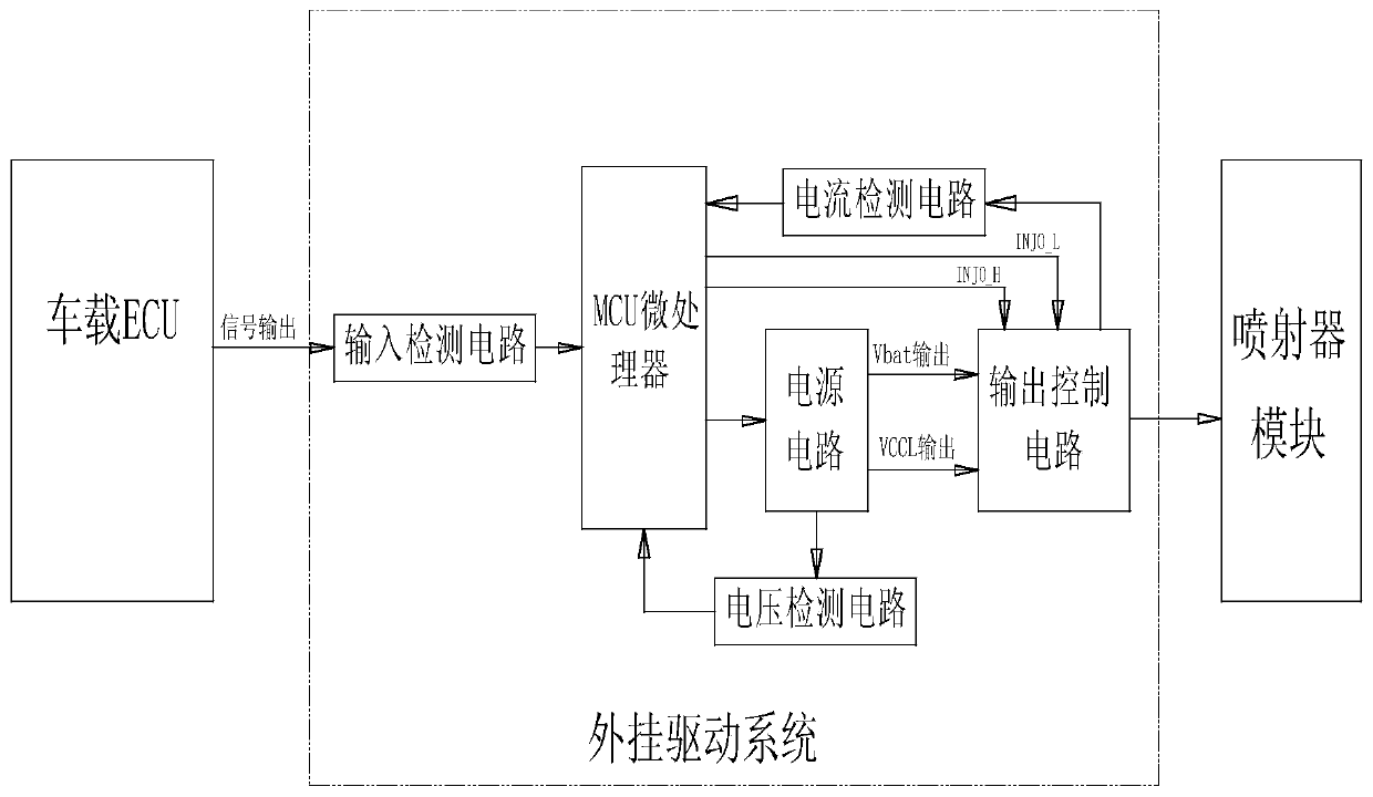
[0054] A solenoid valve injector driving circuit system (see figure 1 ), including a vehicle-mounted ECU, an injector module, and a plug-in drive system, and the plug-in drive system includes an input detection circuit, an MCU microprocessor, a power supply circuit, an output control circuit, a voltage detection circuit, and a current detection circuit, wherein:

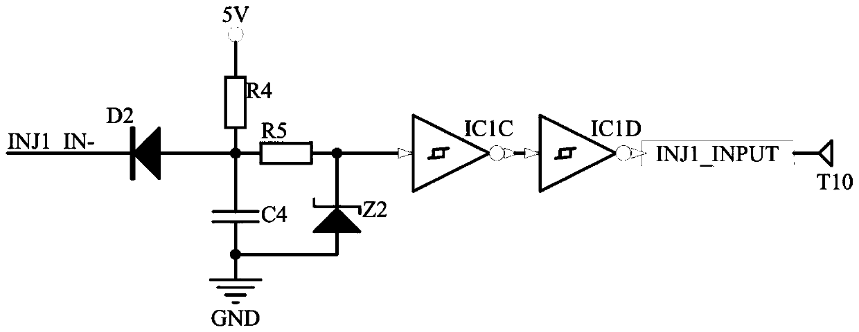
[0055] The input detection circuit is used to detect the input signal of the injector module, the input end of the input detection circuit is connected with the output end of the vehicle-mounted ECU, and the output end of the input detection circuit is connected with the input end of the MCU microprocessor;

[0056] Described MCU microprocessor is as control core, is responsible for the control of each module, and the output end of this MCU microprocessor is connected with the input end of power supply circuit, output control circuit respectively;

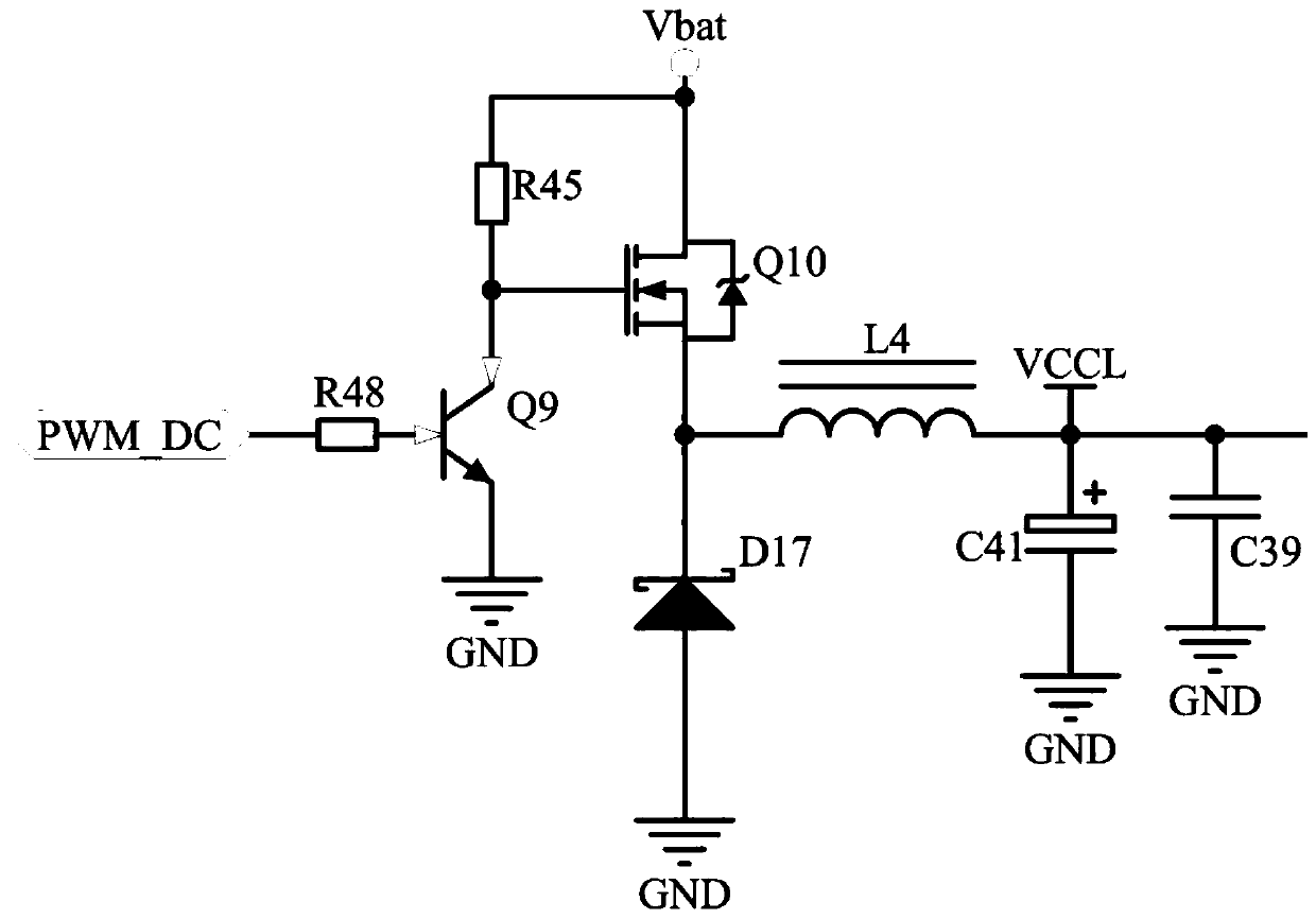
[0057] The power supply circuit is used to provide Vbat voltage or V...


PUM


Abstract

The invention provides a solenoid valve type ejector driving circuit system, and relates to a driving circuit system. The system comprises a vehicle-mounted ECU, an ejector module and an external driving system, wherein the external driving system comprises an input detecting circuit, an MCU microprocessor, a power circuit, an output control circuit, a voltage detecting circuit and a current detecting circuit; the vehicle-mounted ECU is connected to the MCU microprocessor through the input detecting circuit; the output end of the MCU microprocessor is correspondingly connected to the power circuit and the output control circuit; and the power circuit is connected to the ejector module through the output control circuit. According to the system, the current which actually flows through an ejector is detected, and the output voltage of the power circuit is regulated, thus the driving power is reduced on the premise that the flow rate and the atomizing effect of the ejector are not influenced, and as a result, the heating capacity of the ejector is reduced; the ejector can stably reliably work for a long term in high temperature environment; the problem that an electromagnetic coil isburnt out due to long-term electrifying of the ejector is solved; the product reliability and stability are ensured; and the system is easy to popularize and use.

Description

technical field [0001] The invention relates to a driving circuit system, in particular to a driving circuit system of a solenoid valve injector. Background technique [0002] At present, there are two main types of solenoid valve injector drive circuit systems. One is the commonly used voltage drive method, which is driven by discrete components or dedicated integrated chips. The drive is mature and stable, but the power is uncontrollable. The heat is relatively large, especially when used in a high-temperature environment, which requires high manufacturing technology for the injector. Another current drive method is currently available on the market. Only dedicated chips from BOSCH and NXP, but the circuits of these two dedicated chips are relatively complex. Contents of the invention [0003] The technical problem to be solved by the present invention is to provide a driving circuit system of a solenoid valve injector to solve the disadvantages of the prior art that th...

Claims


Application Information

Patent Timeline
Patent Type & Authority Applications(China)
IPC IPC(8): F02M51/06
CPCF02M51/061
Inventor 唐凤君潘俊运劳世元邓宇
Owner LIUZHOU YUANCHUANG EFI TECH
Learn More